Important: When installing new clutch discs in the 1st-reverse brake, the underdrive
brake, the underdrive clutch, the intermediate brake, the forward clutch or
the direct clutch assemblies, the new clutch discs MUST be soaked in Dexron®-III
Automatic Transmission Fluid GM P/N 12346143 or equivalent, two hours prior
to installation. This causes the clutch material on the discs to permeate
with fluid which will aid in ease of assembly and prevent clutch overheating
on first time engagement.
Important: The intermediate brake flange must be installed with the flat side facing
upward and the stepped portion facing down.
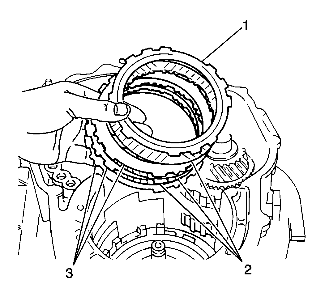
- Install the intermediate
brake flange (1), three intermediate brake discs (2) and 3
intermediate brake plates (3) into the transaxle case in the following
order:
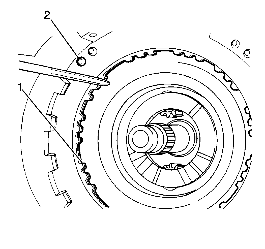
- Align the inner teeth
of the intermediate brake discs (1).
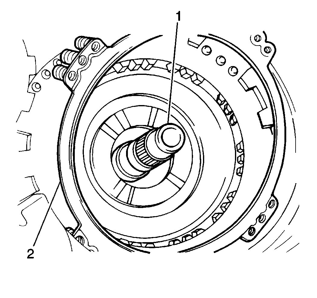
- Install the intermediate
brake piston return spring (2) into the transaxle case.
Notice: Use the correct fastener in the correct location. Replacement fasteners
must be the correct part number for that application. Fasteners requiring
replacement or fasteners requiring the use of thread locking compound or sealant
are identified in the service procedure. Do not use paints, lubricants, or
corrosion inhibitors on fasteners or fastener joint surfaces unless specified.
These coatings affect fastener torque and joint clamping force and may damage
the fastener. Use the correct tightening sequence and specifications when
installing fasteners in order to avoid damage to parts and systems.
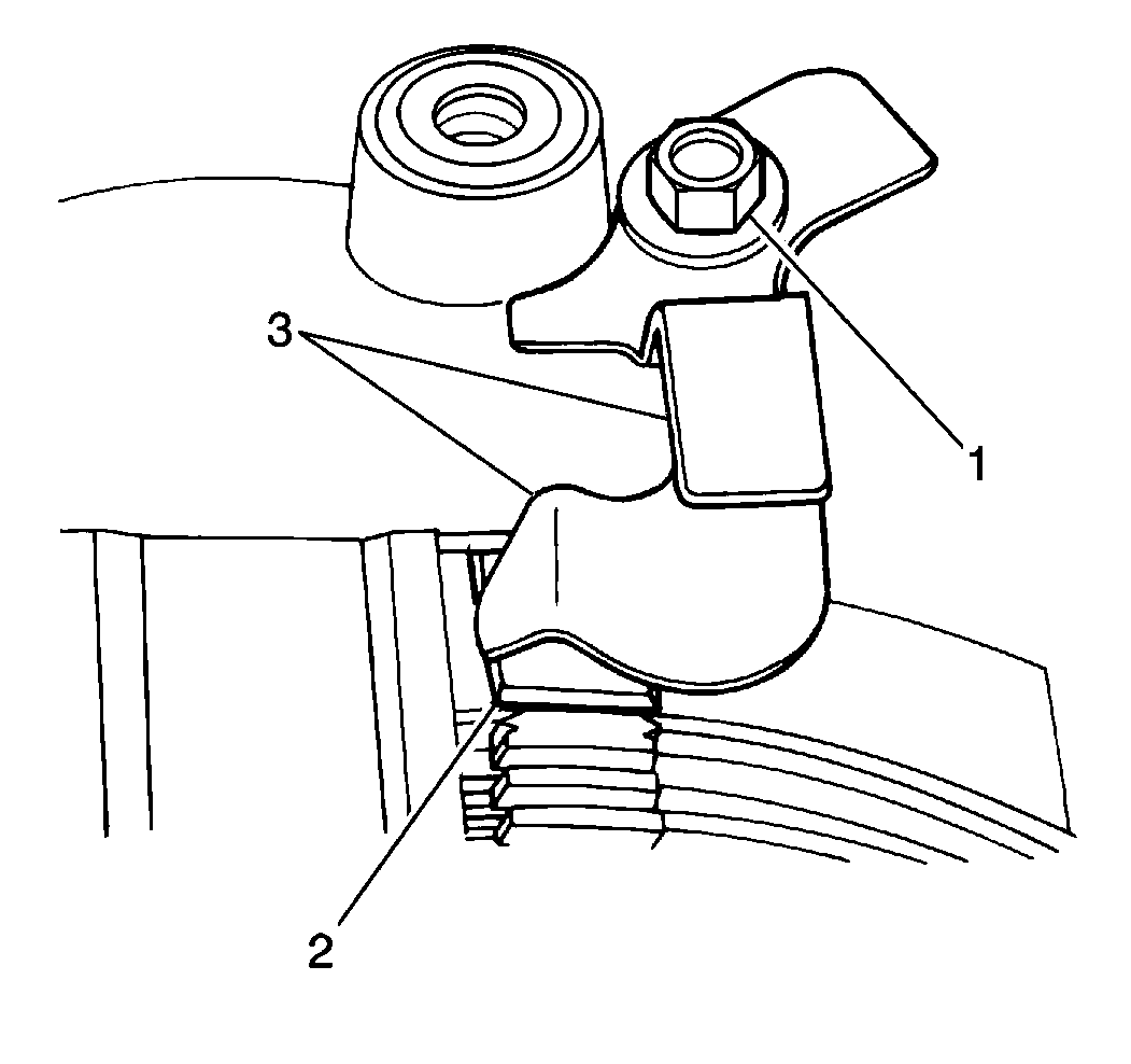
- Install the 2nd
coast brake band guide (3) into the transaxle case. Secure with a
bolt.
Tighten
Tighten the 2nd coast brake band guide bolt to 10 N·m (89 lb in).
Notice: Use the correct fastener in the correct location. Replacement fasteners
must be the correct part number for that application. Fasteners requiring
replacement or fasteners requiring the use of thread locking compound or sealant
are identified in the service procedure. Do not use paints, lubricants, or
corrosion inhibitors on fasteners or fastener joint surfaces unless specified.
These coatings affect fastener torque and joint clamping force and may damage
the fastener. Use the correct tightening sequence and specifications when
installing fasteners in order to avoid damage to parts and systems.
Important: The groove in the intermediate brake drum must line up with the 2nd
coast brake band guide bolt hole. The 2nd coast brake band guide bolt aligns
the intermediate brake drum so that the intermediate brake apply tube
aligns with the intermediate brake piston apply passage.
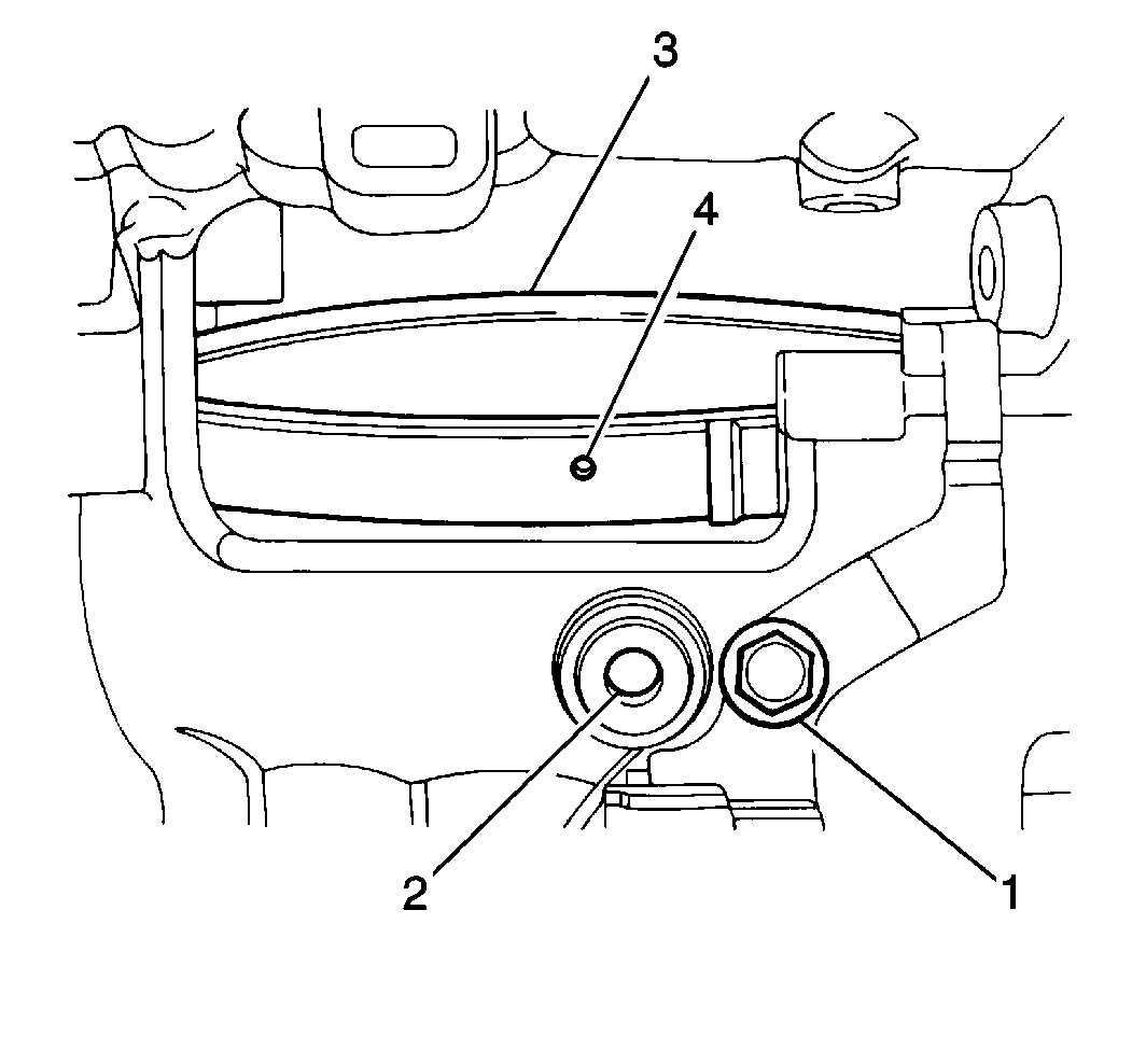
- Install the intermediate
brake drum (3) and piston into the transaxle case. Align the slot
in the immediate brake drum with the 2nd coast brake band guide bolt (1).
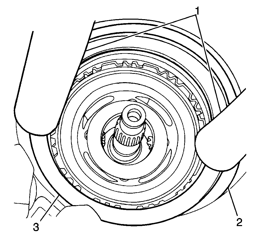
- Push down the intermediate
brake drum using two hammer handles (1). Push down until you can install
the intermediate brake snap ring (2). Do not use metal tools in
order to push down on the intermediate brake drum (3).
- Install the intermediate brake drum snap ring into the transaxle
case.
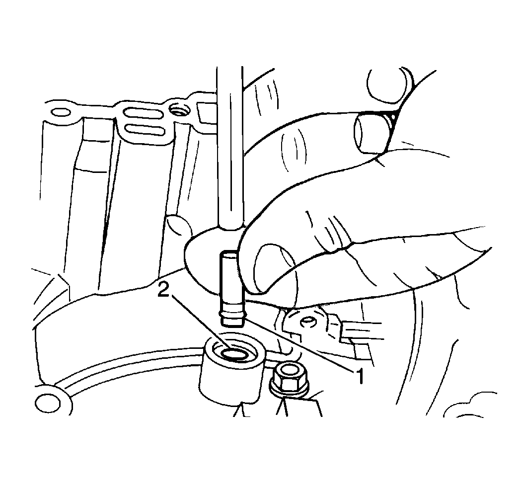
- Temporarily install the
intermediate brake apply tube (1) into the transaxle case in order
to inspect the intermediate brake piston operation.
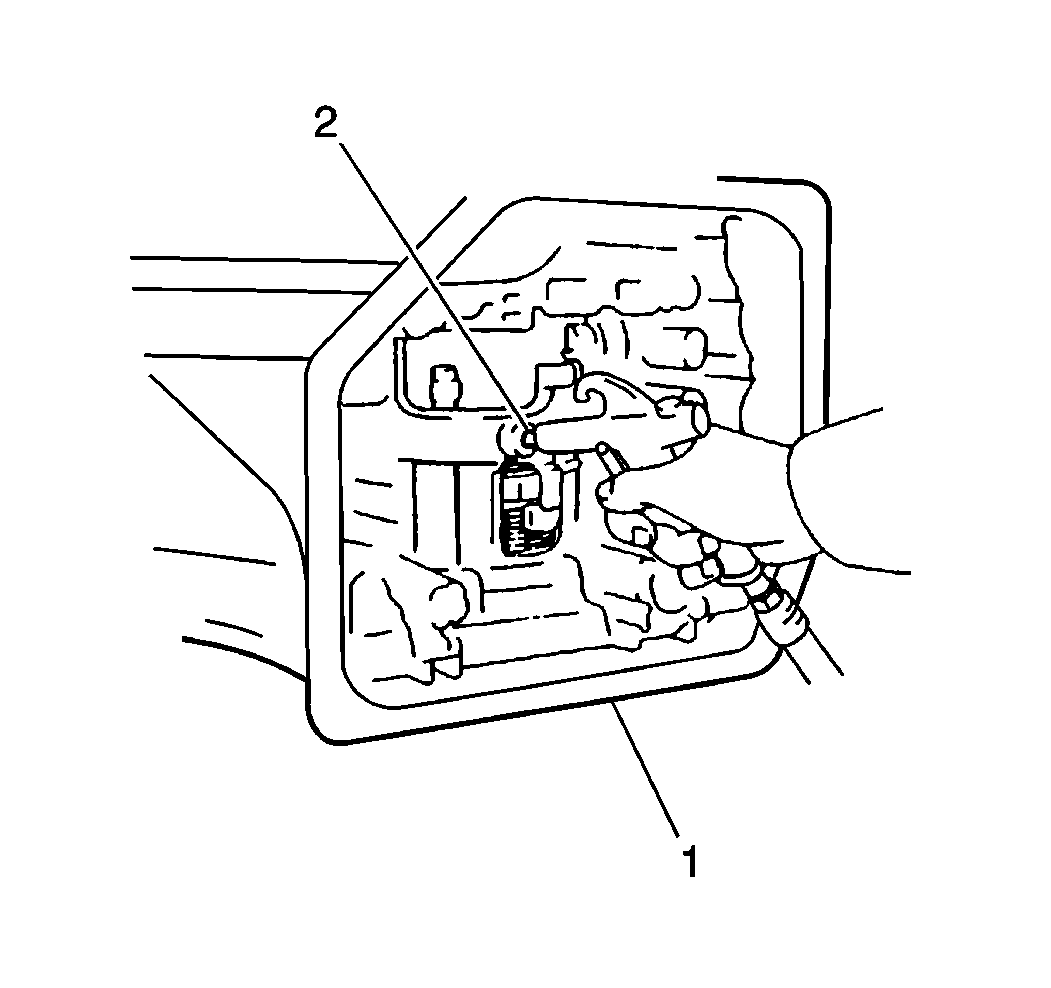
- Inspect the intermediate
brake piston operation by applying 392-785 kPa (57-114 psi)
of compressed air into the intermediate brake apply tube.
| • | Verify that the intermediate brake piston applies and releases
smoothly. |
| • | Remove the intermediate brake apply tube (2) from the transaxle
case (1). |


