- Note the position of the throttle valve adjusting screw (1).
- Note the position of the primary regulator valve plunger sleeve (2).
- Remove the following components from the upper valve body (2):
- Remove one bolt and the torque converter clutch (TCC) solenoid (3) from the lower valve body.
- Remove one O-ring from the TCC solenoid.
- Remove the following components from the lower valve body:
- Remove the two O-rings from the shift solenoids No. 1 and 2.
- Remove the following components from the lower valve body (2):
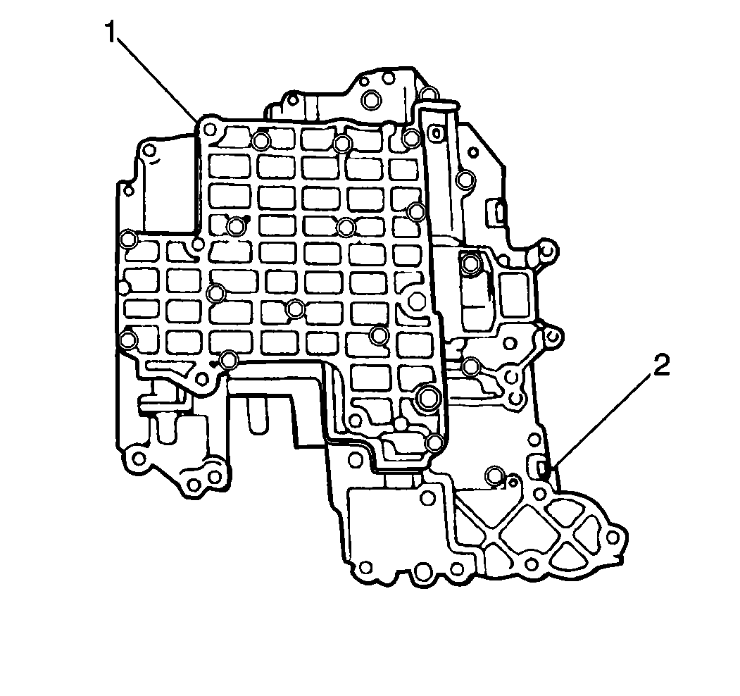
- Remove 22 bolts from the upper valve body (1).
- Remove the lower valve body (1) with the spacer plate (2) and the gasket from the upper valve body (3).
- Remove the following components from the lower valve body (3):
- Remove the following components from the lower valve body (3):
- Remove the check balls from the upper valve body.
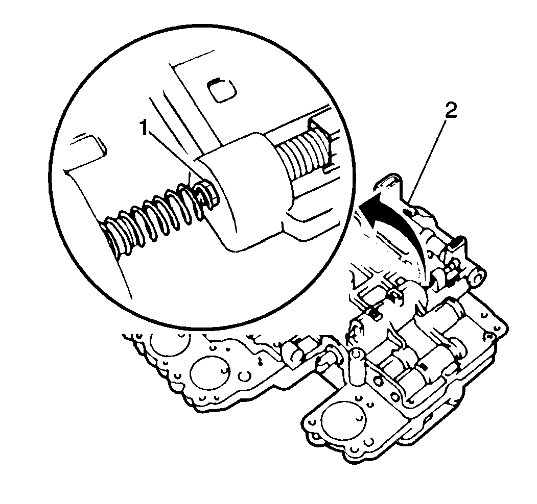
Important: Note the positions of the throttle valve adjusting screw and the primary regulator valve plunger sleeve before disassembling the valve body. The throttle valve opening will change with the throttle valve adjusting screw position. Some units do not require a throttle valve adjusting screw. However, if the unit includes a throttle valve adjusting screw and it is removed or replaced during valve body service, the new or reused throttle valve adjusting screw must be installed in the same position from which it was removed. Line pressure will change with the position of the primary regulator valve plunger sleeve. If the primary regulator valve plunger sleeve is removed during valve body service, verify that the primary regulator valve plunger sleeve is installed in the same position from which it was removed.


| • | One bolt |
| • | The throttle valve cam (1) |
| • | The sleeve |
| • | The return spring |
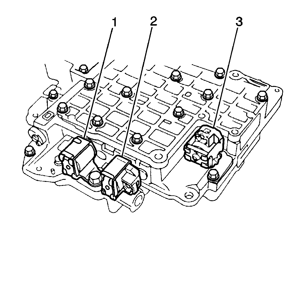
| • | One bolt |
| • | Shift solenoid No 1 (1) |
| • | Shift solenoid No 2 (2) |

| • | One bolt (1) |
| • | The pressure relief valve retainer |
| • | The spring |
| • | The check ball |

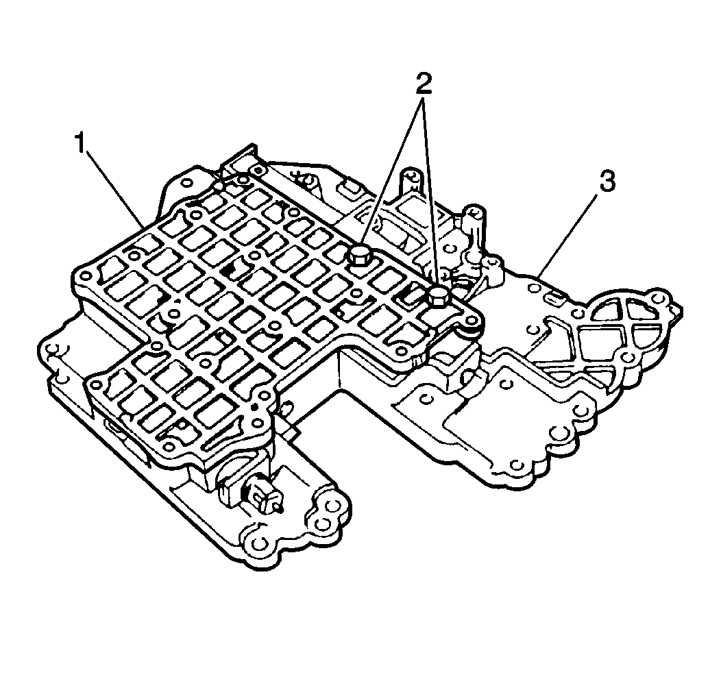
| • | Two bolts (2) |
| • | The lower valve body cover (1) |
| • | The gasket |
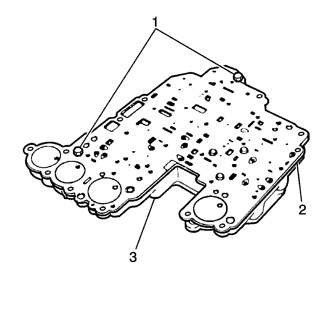
| • | One screw (1) |
| • | The spacer plate (2) |
Important: There are 9 check balls in the upper valve body. Two check balls are larger than the remaining 7 balls. Note the positions of the check balls to ensure correct assembly.
