For 1990-2009 cars only
Removal Procedure
- Raise the vehicle. Refer to Lifting and Jacking the Vehicle in General Information.
- Remove the tire and wheel assembly. Refer to Tire and Wheel Removal and Installation in Tires and Wheels.
- Remove the brake drum.
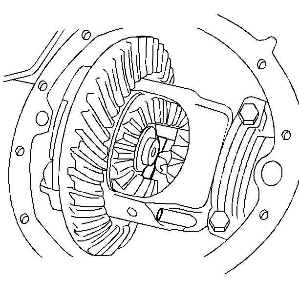
- Remove the rear axle housing cover. Refer to Carrier Cover Gasket Replacement .
- Remove the pinion shaft lock bolt. Refer to Differential Case Replacement.
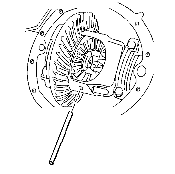
- Remove the pinion shaft.
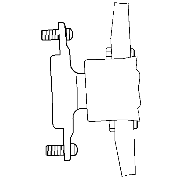
- Push the axle shaft in toward the center of the vehicle. Remove the C-lock from the button end of the axle shaft.
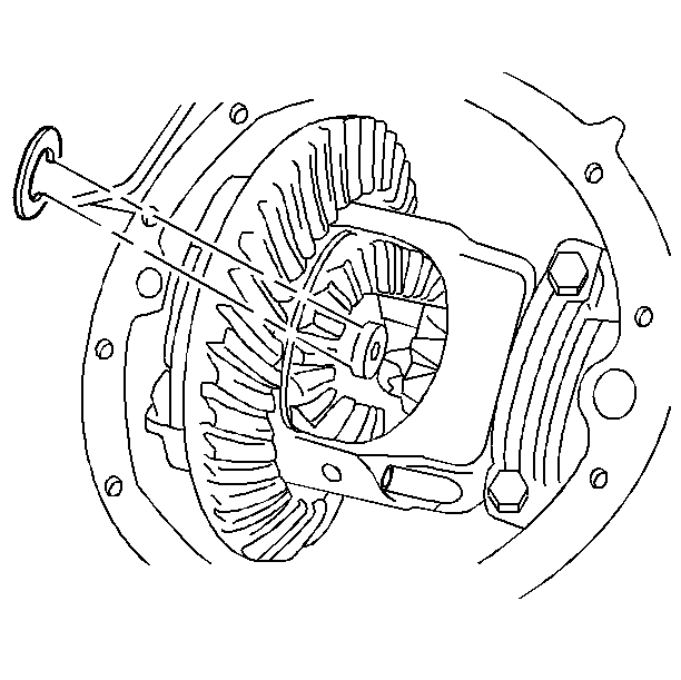
- Remove the axle shaft from the axle housing. Mark the shaft as left or right.
Installation Procedure
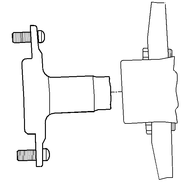
- Lubricate the axle shaft wheel bearing surface and the oil seal surface with axle lubricant. Refer to Fluid and Lubricant Recommendations in Maintenance and Lubrication.
- Install the axle shaft into the axle housing.
- Install the C-lock on the axle shaft. Pull the axle shaft outward so the C-lock seats in the counterbore of the rear axle side gear.
- Install the pinion shaft through the case and the pinions.
- Install the pinion shaft lock bolt. Refer to Differential Replacement.
- Install the rear axle housing cover. Refer to Carrier Cover Gasket Replacement .
- Install the brake drum.
- Install the tire and wheel assembly. Refer to Tire and Wheel Removal and Installation in Tires and Wheels.
- Lower the vehicle.
- Inspect the rear axle operation.
Important:
• Use the correct axle on the axle's corresponding side. • Do not damage the oil seal. • The splined end of the axle shaft must engage the splines of the
rear axle side gear.
