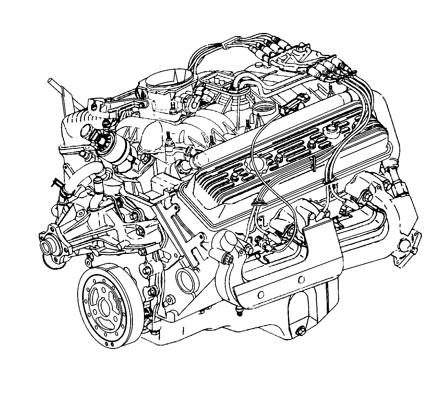
Cylinder Block
The engine block is made of cast iron and has eight cylinders arranged in a V shape with four cylinders in each bank. The cylinder block is a one piece casting with the cylinders encircled by coolant jackets.
Cylinder Head
The cylinder heads are made of cast iron. The valve guides and valve seats are machined surfaces integral to the cylinder head. The 5.7 L heavy duty applications have pressed in exhaust valve seats. The spark plugs are located between the intake and exhaust ports.
Camshaft
A steel engine camshaft is supported by five camshaft bearings pressed into the engine block. The camshaft sprocket, mounted to the front of the engine camshaft, is driven by the crankshaft sprocket through a camshaft timing chain.
Motion from the engine camshaft is transmitted to the valves by hydraulic roller valve lifters, valve pushrods, and ball-pivot type valve rocker arms.
Crankshaft
The crankshaft is made of cast nodular iron. The crankshaft is supported by five crankshaft bearings. The crankshaft bearings are retained by the crankshaft bearing caps, which are machined with the engine block for proper alignment and clearances. Light duty 5.0 L and 5.7 L engines have two bolts per crankshaft bearing cap. The heavy duty 5.7 L engines have four bolts per crankshaft bearing cap, on bearing caps 2, 3, and 4. The number 5 crankshaft bearing cap at the rear of the engine is the end thrust bearing cap. The four connecting rod journals (two connecting rods per journal) are spaced 90 degrees apart. The crankshaft position sensor reluctor ring is pushed onto the front of the crankshaft. The crankshaft position sensor reluctor ring has four lugs used for crankshaft timing and it is constructed of powdered metal. The reluctor ring has an interference fit onto the crankshaft and an internal keyway for correct positioning.
Pistons and Connecting Rods
The pistons are made of cast aluminum that use two compression rings and one oil control ring assembly. The piston is a low-friction, lightweight design with a flat top and barrel-shaped skirt. The piston pins are chromium steel. The piston pins have a floating fit in the piston and are retained by a press fit in the connecting rod assembly. The connecting rods are made out of either forged powdered metal or forged steel. The connecting rods are machined with the connecting rod cap installed for proper clearances and alignment.
Valve Train
The valve train is a ball pivot type. Motion is transmitted from the camshaft through the hydraulic roller valve lifters and tubular valve pushrods to the valve rocker arms. The valve rocker arm pivots on a ball in order to open the valve. The hydraulic roller valve lifters keep all parts of the valve train in constant contact. The valve rocker arm ball is retained on the valve rocker arm ball stud with a locking nut. The valve rocker arm ball studs are pressed into the cylinder head.
Intake Manifold
The intake manifold is a two piece design. The upper intake manifold portion is made from a composite material and the lower intake manifold portion is cast-aluminum. The throttle body mounts to the upper intake manifold. The lower intake manifold has an exhaust gas recirculation (EGR) port cast into the manifold for mixture of exhaust gases with the fuel and air mixture. The EGR valve mounts to the lower intake manifold.
The Central Sequential Multiport Fuel Injection, Central (SFI) system uses multiple injectors to meter and distribute fuel to each engine cylinder. The Central (SFI) unit is retained by a bracket bolted to the lower intake manifold. The TBI fuel meter also houses the pressure regulator. Metal inlet and outlet fuel lines and nylon delivery tubes independently distribute fuel to each cylinder through nozzles located at the port entrance of each manifold runner where the fuel is atomized.
