For 1990-2009 cars only
Tools Required
| • | J 5830-02 Valve Guide Reamer Set |
| • | J 8001 Dial Indicator Set |
- Measure the valve stem-to-guide clearance.
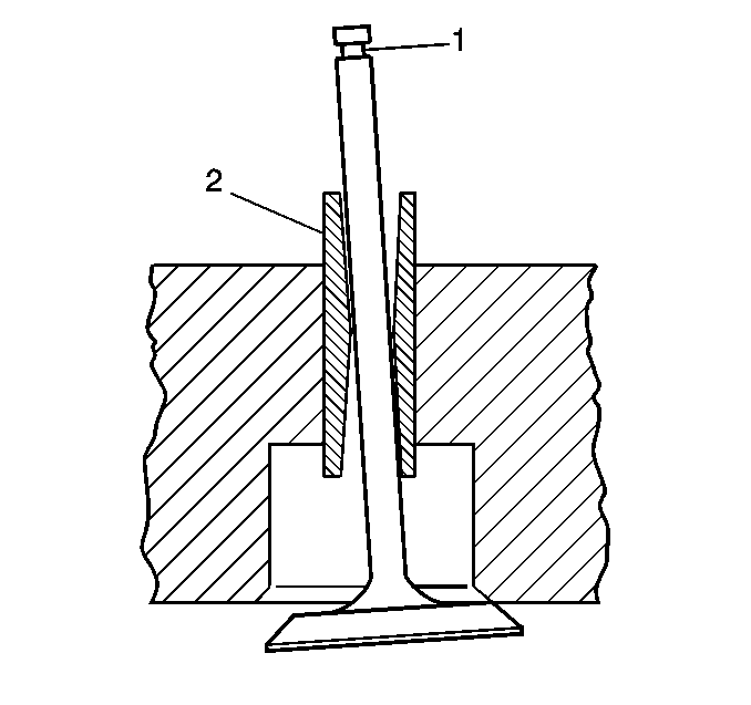
- Improper valve stem (1) to valve guide (2) clearance may cause excessive oil consumption.
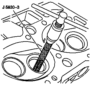
- Use the J 5830-3 in order to ream the exhaust valve guide in order to achieve the correct valve stem-to-guide clearance.
- Always recondition the exhaust valve seat after reaming the exhaust valve guide bores and installing new exhaust valves.
- Inspect the valves for the following:
- Inspect the valve contact surface for the following:
- Reconditioning of the valves and valve seats:
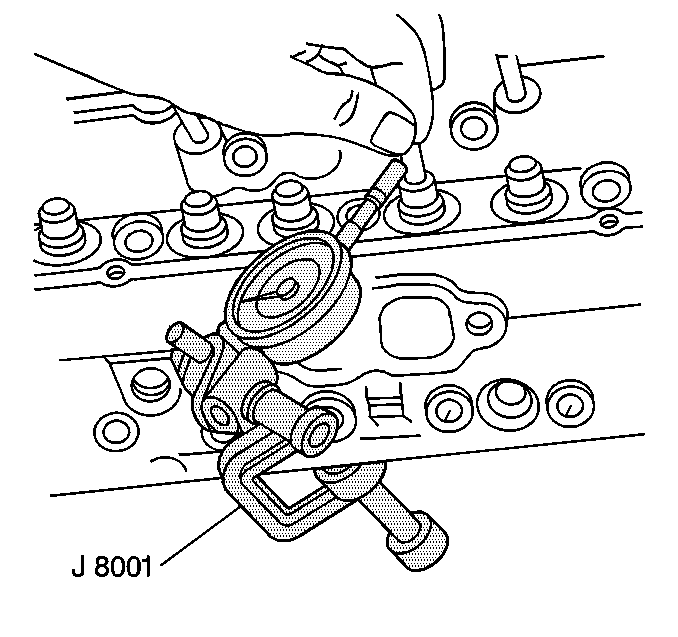
Refer to Cylinder Head Cleaning and Inspection.
Caution: Wear safety glasses in order to avoid eye damage.
Important: Exhaust valves with excessive valve stem-to-guide clearance must be replaced with the available service valve that has an 0.0774 mm (0.0305 in) oversize valve stem. The intake valves are NOT available with oversize valve stems. Replace the cylinder head if after using a NEW intake valve in order to measure the valve stem-to-guide clearance, the valve stem-to-guide clearance is not within specifications.
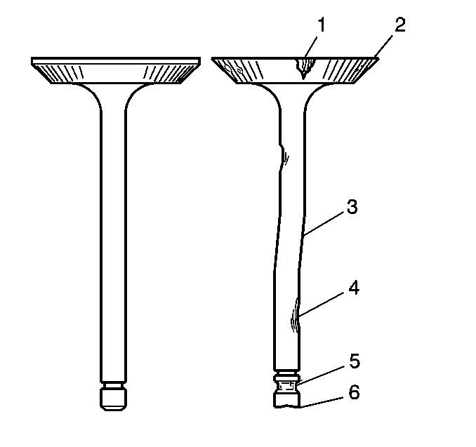
| • | Burnt or damaged areas (1) |
| • | Undersized margin (2) |
| • | Bent stem (3) |
| • | Scoring or other damage to the stem (4) |
| • | Worn key groove (5) |
| • | Worn stem tip (6) |
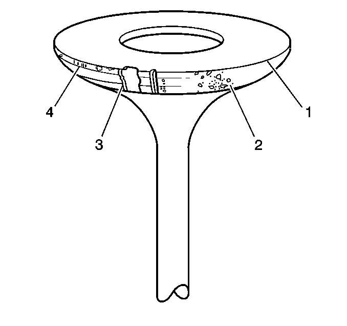
| • | Undersized margin (1) |
| • | Pitted surface (2) |
| • | Burnt or eroded areas (3) |
| • | Acceptable edge (margin) (4) |
| • | Valves with excessive damage must be replaced. |
| • | Minor imperfections of the valve or valve seat may be repaired. |
| • | The valves must seat perfectly for the engine to deliver optimum power and performance. |
| • | Cooling the valve heads is another important factor. Good contact between each valve and valve seat in the cylinder head is necessary to insure that the heat in the valve head is properly carried away. |
| • | Regardless of what type of equipment is used, it is essential that the valve guide bores are free from carbon or dirt in order to ensure the proper centering of the pilot in the valve guide. |
| • | The valve seats should be concentric to within 0.05 mm (0.002 in) total indicator reading. |
| • | Reface pitted valves on a valve refacing machine in order to ensure the correct relationship between the valve head and the valve stem. |
| • | Replace the valve if the valve stem is excessively worn or warped. |
| • | Replace the valve if the edge of the valve head is less than 0.79 mm (0.031 in) thick after grinding. |
| • | Several different types of equipment are available for reconditioning valves and valve seats. Follow the equipment manufacturer's recommendations for equipment use to attain the proper results. |
