Tools Required
| • | J 3289-20 Holding Fixture |
| • | J 35664 Pinion Shaft Bearing Installer |
| • | J 44856 Pinion Depth Shim Selector |
| • | J 44861 Pinion Inner Bearing Race Installer |
| • | J 44864 Pinion Nut Wrench |
| • | J 44865 Spline Socket |
| • | J 44869 Assembly Holding Fixture |
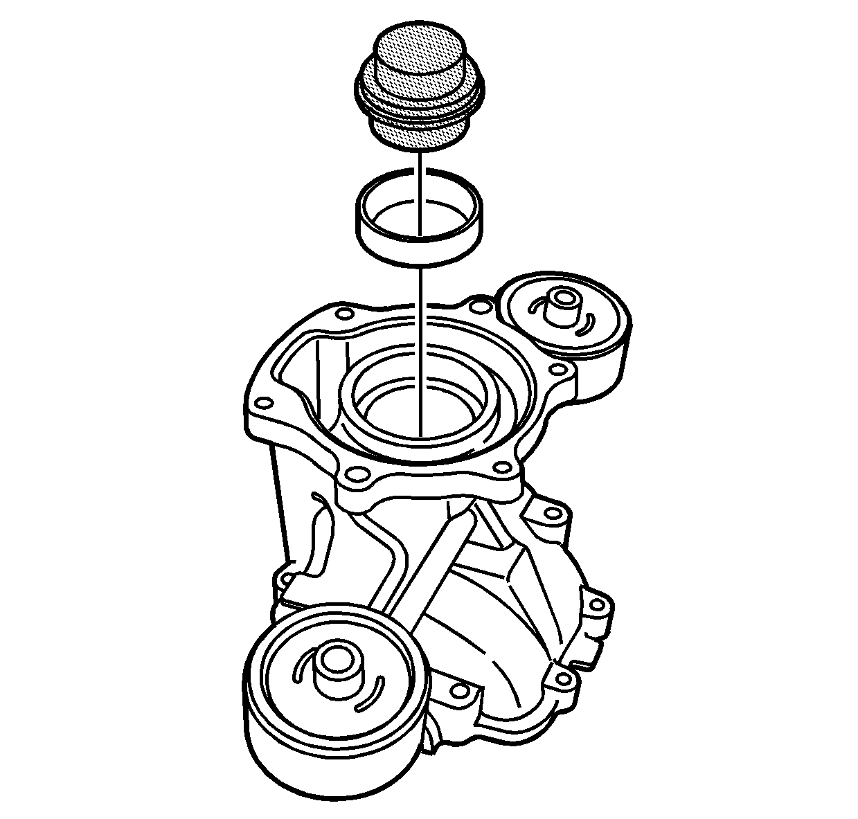
- Using axle lube, lightly lubricate the bearing race. Place the J 44861 inside the race, using a press, install the race.
- Inspect the race to ensure it is properly seated.
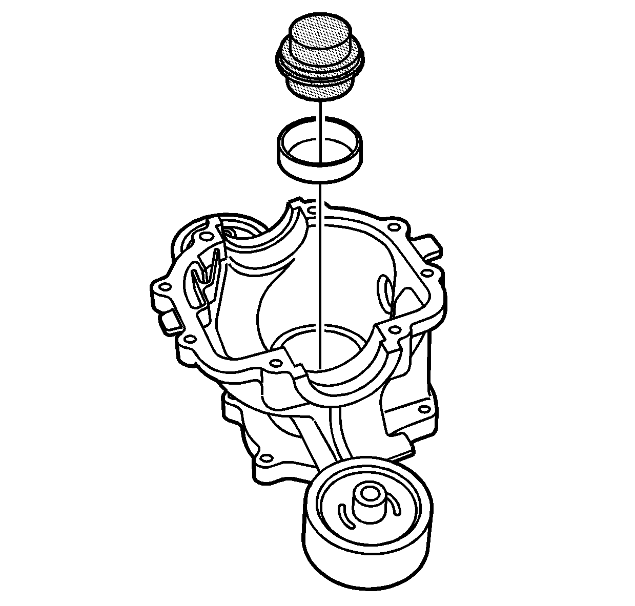
- Using axle lube, lightly lubricate the bearing race. Place the J 44861 inside the race using a press, install the race.
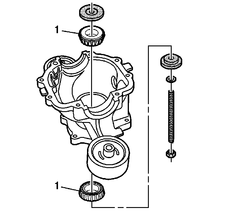
- Install the J 44856-2, -3, -4 on the pinion bearings (1).
- Hold the shaft.
- Rotate the stud assembly while inspecting the rolling torque.
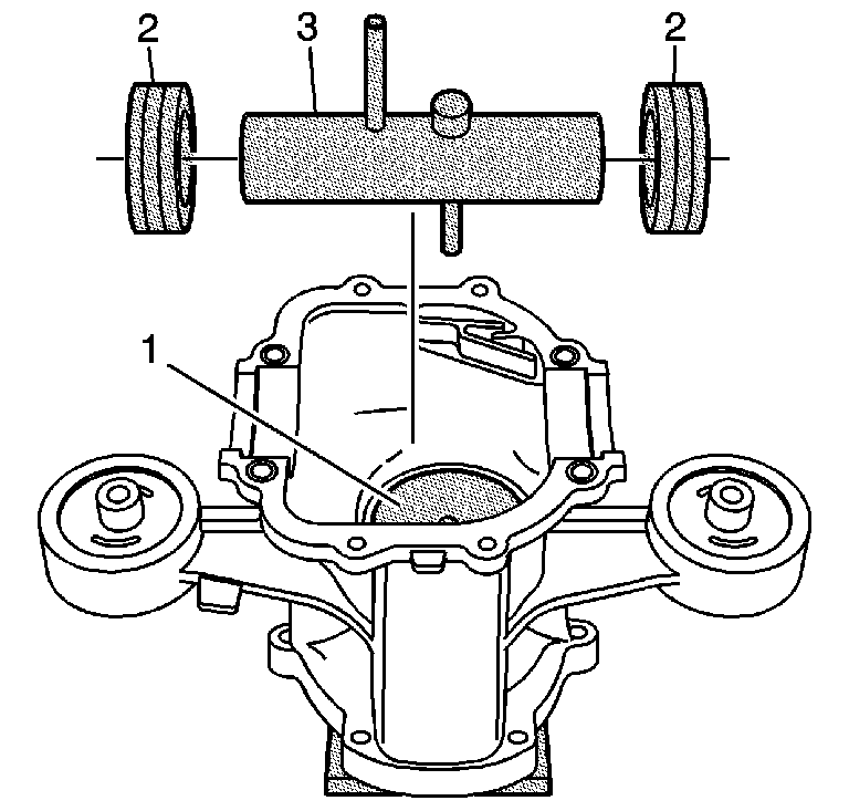
- Turn the housing over so the J 44856-3, (1) pinion gage plate is up.
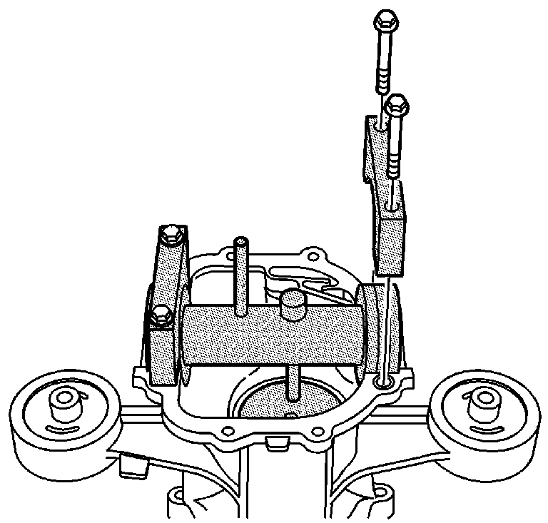
- Install the J 44856-5 (2) master bearings on the J 44856-1 (3) arbor and place it in the differential bearing bores.
- Install the retaining caps J 44856-9 over the master bearings, using 2 M10 rear cover bolts and snug the bolts.
- Install the dial indicator on the arbor post.
- Rotate the J 44856-1 so that the gage pin is not in contact with the J 44856-3 gage block and zero the dial indicator.
- Lift the gage pin and rotate the J 44856-1. Drop the gage pin onto the J 44856-3 pinion gage block.
- Rock the arbor back and forth slightly and record the maximum reading from the dial indicator.
- Remove the pinion shimming tools J 44856 .
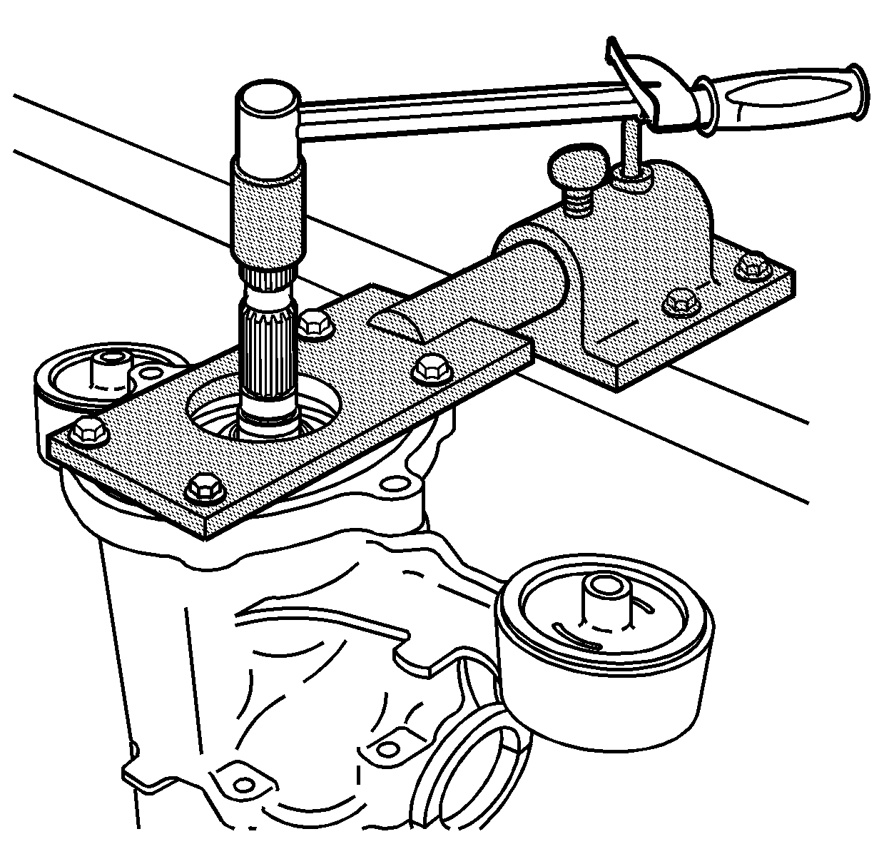
- Using the J 35664 , position the pinion shaft (3) into a press, install the determined shim (2) and bearing (1) on the shaft.
- Install the pinion shaft (4), the collapsible spacer (3) and the bearing (1) into the differential housing (2).
- Position the pinion shaft and differential housing into a press in order to press the bearing on the shaft using the J 35664 .
- Install the differential housing on the J 44869 using 4 clutch cover bolts (1). Install the housing and fixture into the J 3289-20 (2) base.
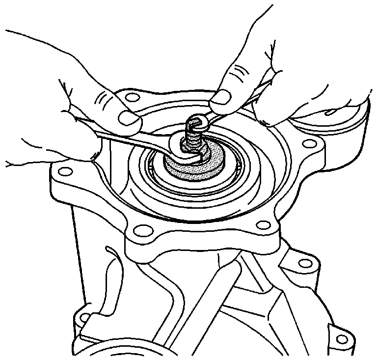
- Install a NEW pinion nut on the pinion shaft.
- Place the J 44865 (1) and breaker bar over the splines on the pinion shaft.
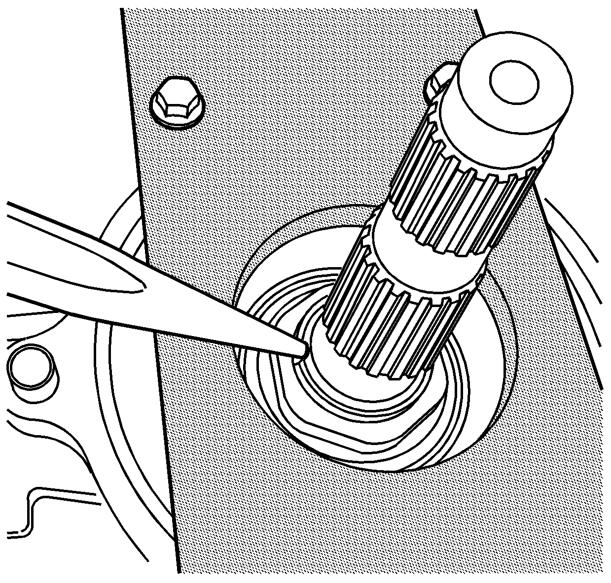
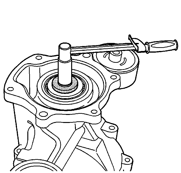
- Remove the J 44864 . Place the J 44865 on a needle type torque wrench, rotate the shaft, inspecting the rolling torque.
- When the rolling torque is reached use a punch to stake the nut on the pinion shaft flats.
Notice: Use the correct fastener in the correct location. Replacement fasteners must be the correct part number for that application. Fasteners requiring replacement or fasteners requiring the use of thread locking compound or sealant are identified in the service procedure. Do not use paints, lubricants, or corrosion inhibitors on fasteners or fastener joint surfaces unless specified. These coatings affect fastener torque and joint clamping force and may damage the fastener. Use the correct tightening sequence and specifications when installing fasteners in order to avoid damage to parts and systems.
Important: Lightly lubricate the bearing rollers with axle lube.
Tighten
Tighten the nut to obtain 1.69 N·m (15 lb in)
of pinion bearing preload.
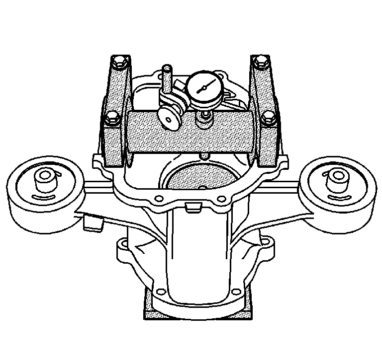
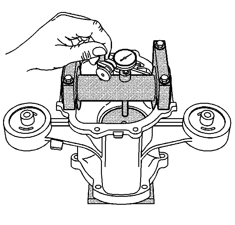
Subtract this measurement from 2.54 mm (0.100 in) this equals shim thickness.
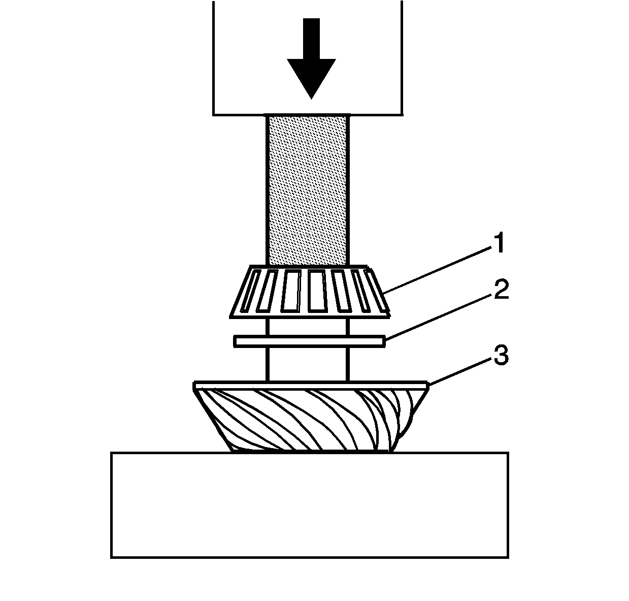
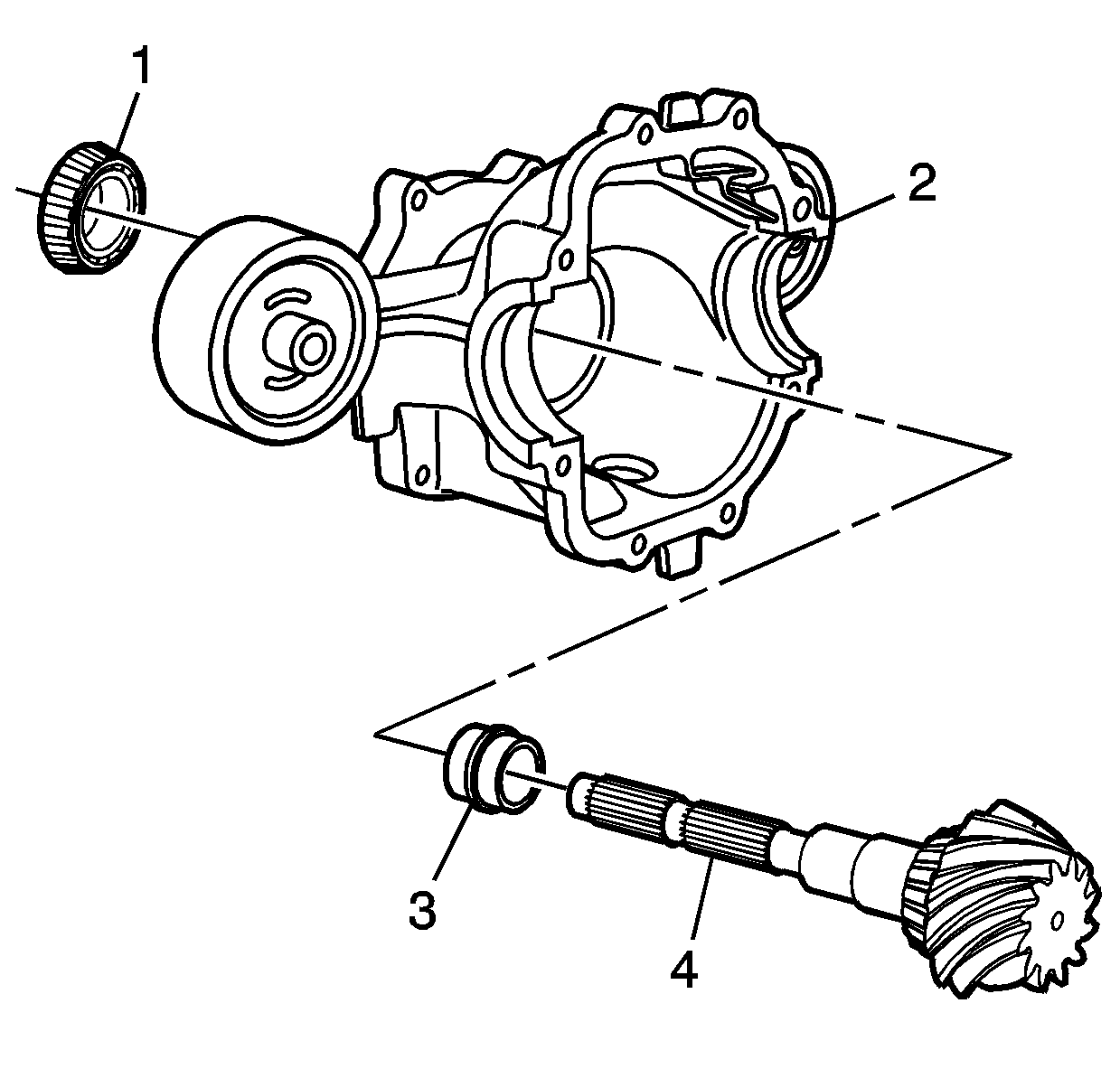
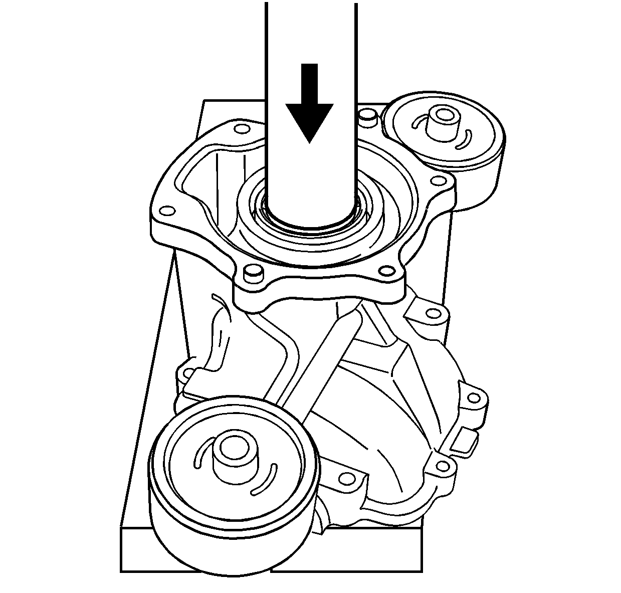
Important: The rear face of the pinion shaft must be supported in order to install the pinion shaft and bearing.
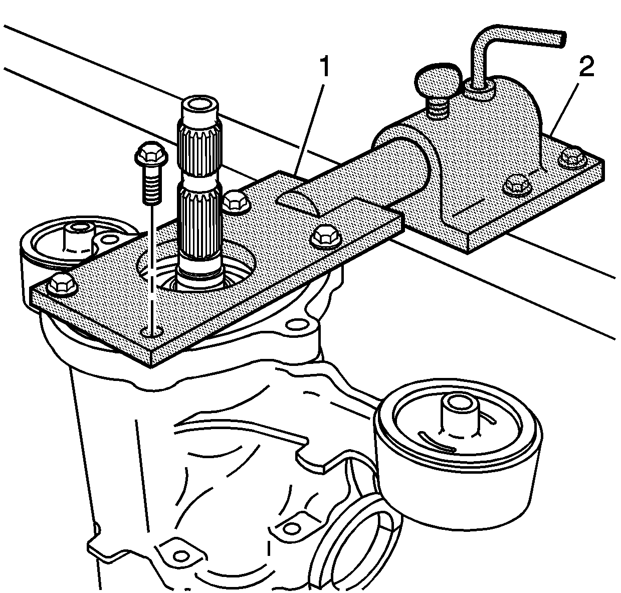
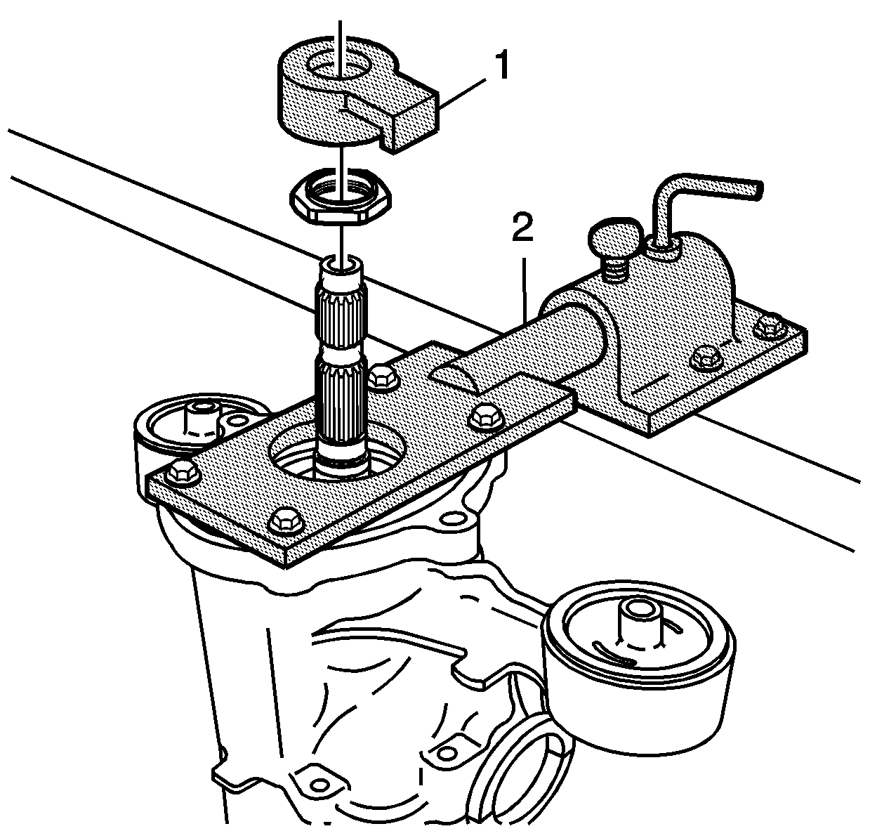
Place the J 44864 (1) over the pinion shaft (1). Turn the pinion shaft by hand to align the hex nut and the J 44864 to the flats of the J 44869 (2).
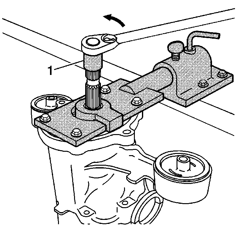
Tighten
Tighten the nut in the left handed direction in small increments as
needed, to apply bearing preload.
Tighten
The rolling torque is 1.69 N·m (15 lb in).
