For 1990-2009 cars only
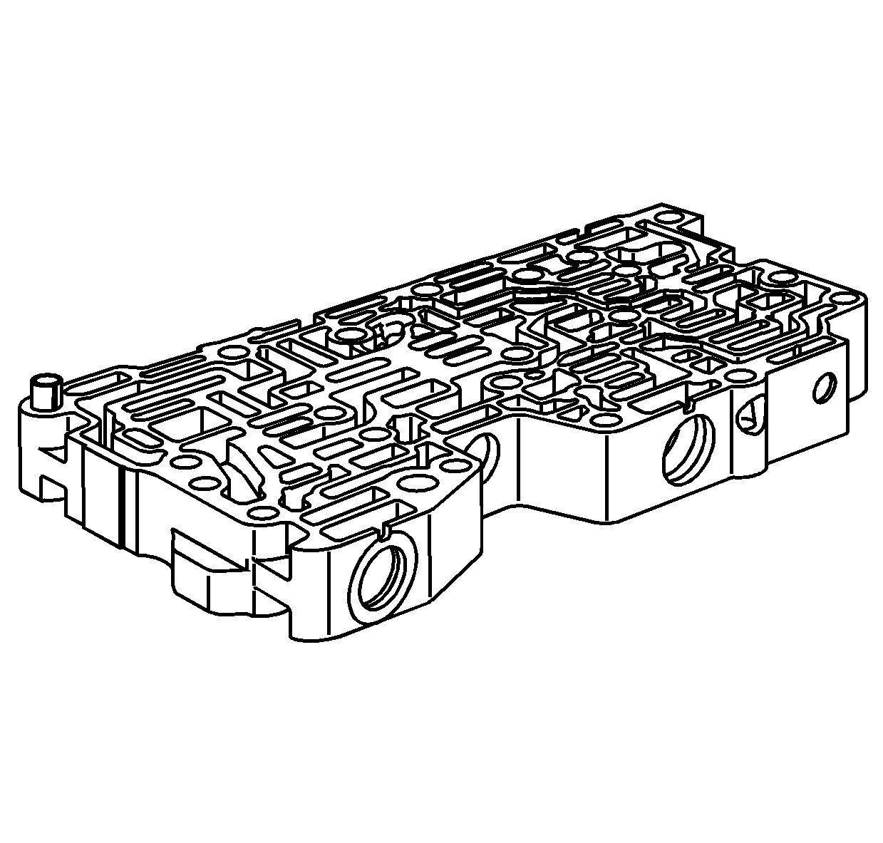
- Using clean solvent, thoroughly clean the control valve body assembly, valves, springs, and all other components.
- Using compressed air, dry all components.
- Inspect the valve body casting for the following conditions:
- During assembly, inspect the control valve body components for the following:
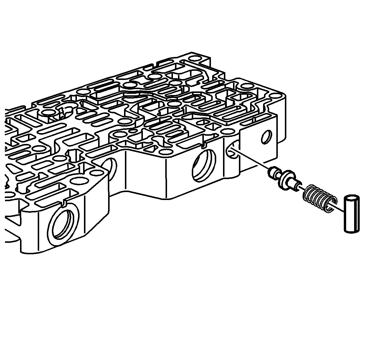
- Inspect the control solenoid valve locator pin in the control valve body assembly for damage. Replace the pin if necessary.
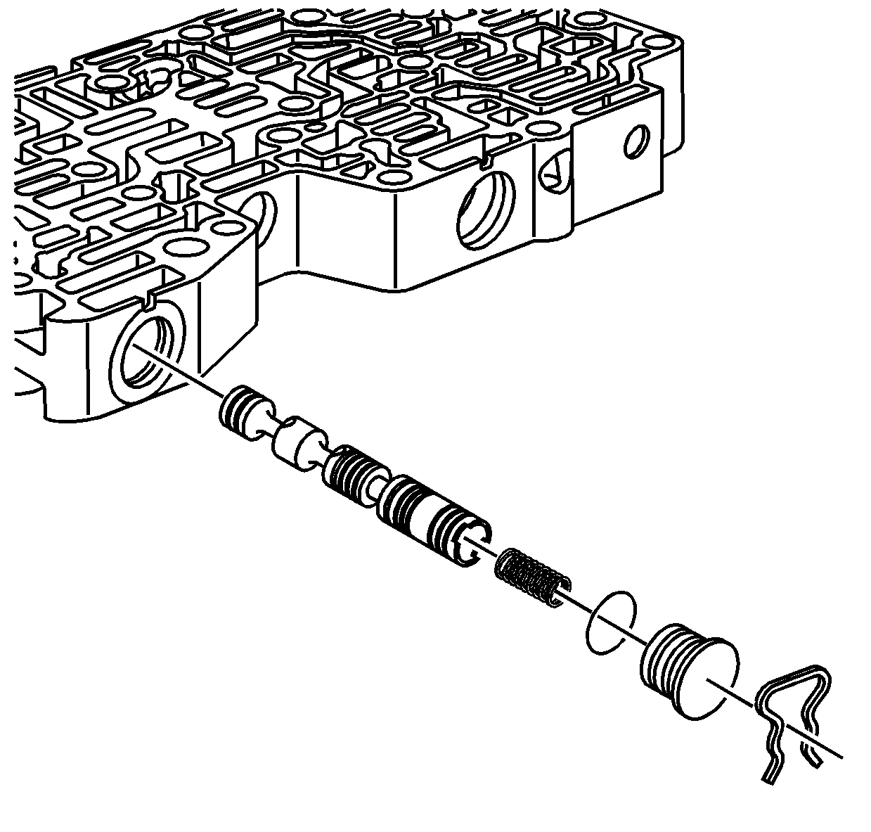
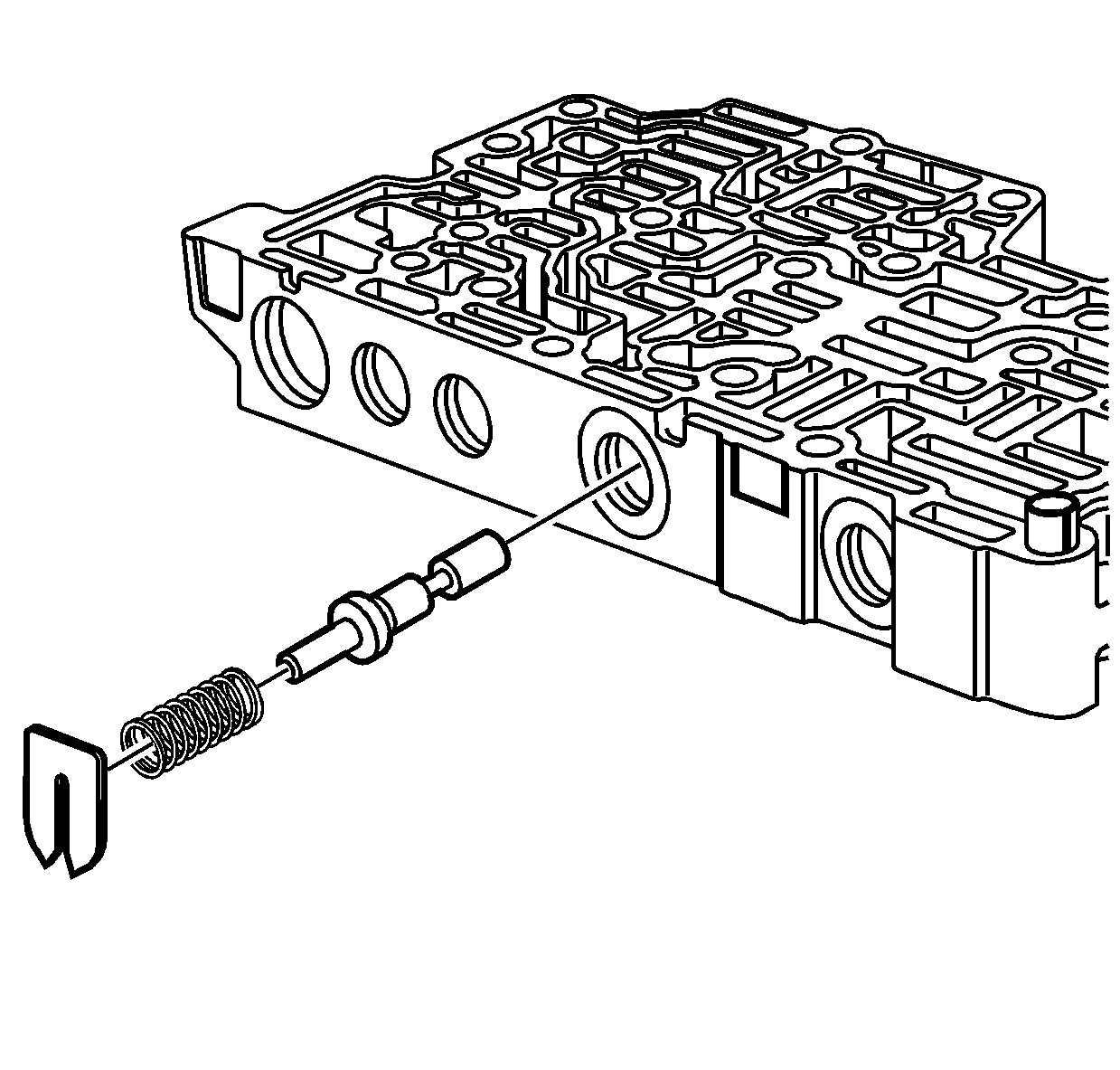
- Install the clutch boost valve into the control valve body assembly.
- Install the clutch boost valve spring.
- Install the control solenoid valve locator pin.
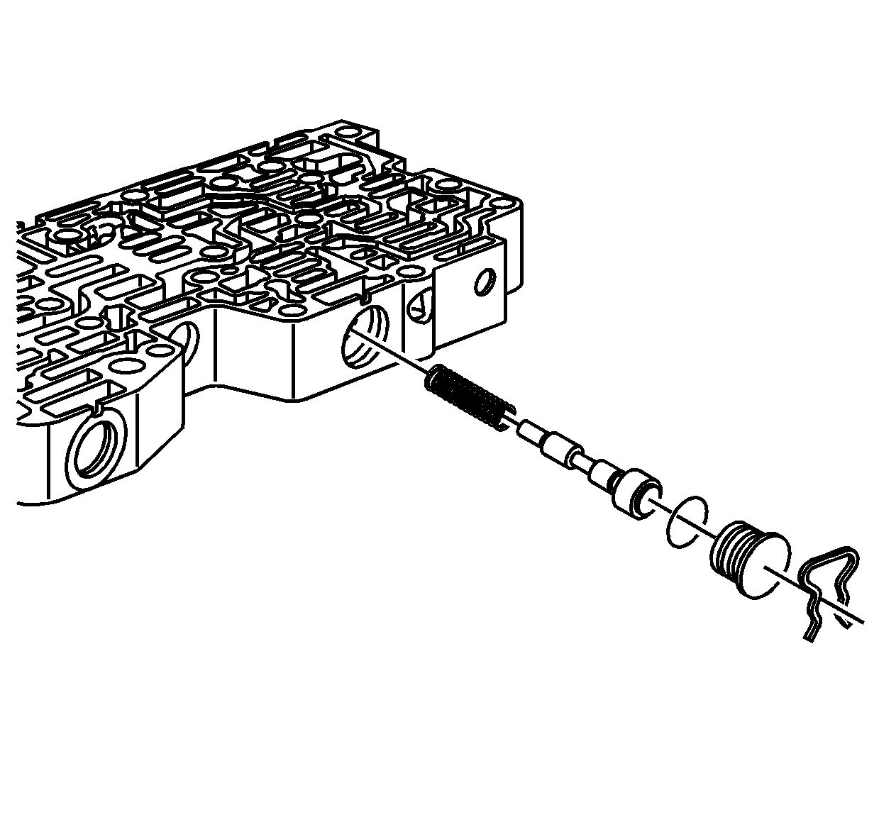
- Install the spring for the TCC regulator apply valve.
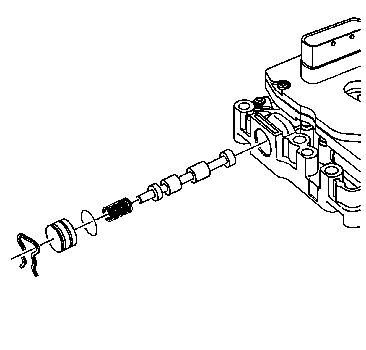
- Install the TCC regulator valve.
- Install a NEW bore plug - O-ring - seal on the bore plug for the TCC regulator valve.
- Install the bore plug for the TCC regulator valve.
- Install the bore plug retainer for the TCC regulator valve.
- Install the spring for the variable ratio control valve.
- Install the variable ratio control valve lever assembly.
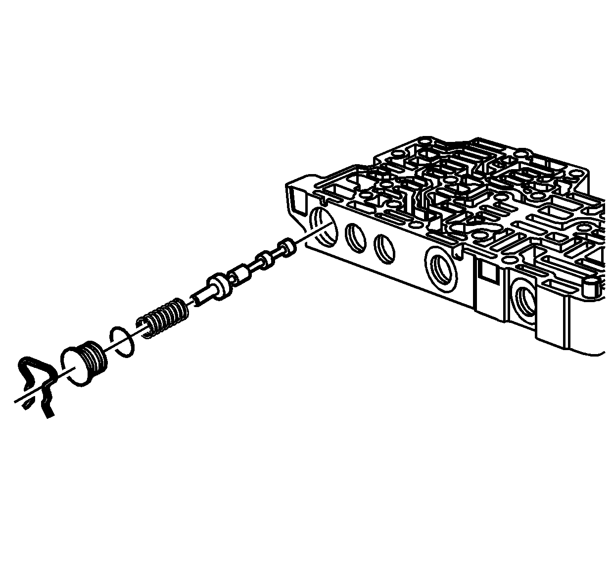
- Install the line 1 pressure regulator valve.
- Install the line 1 pressure regulator valve spring.
- Install a NEW bore plug - O-ring - seal on the bore plug for the line 1 pressure regulator valve.
- Install the bore plug for the line 1 pressure regulator valve.
- Install the bore plug retainer for the line 1 pressure regulator valve.
- Install the forward and reverse clutch valve.
- Install the spring for the forward and reverse clutch valve.
- Install a NEW bore plug - O-ring - seal on the bore plug for the forward and reverse clutch valve.
- Install the bore plug for the forward and reverse clutch valve.
- Install the bore plug retainer for the forward and reverse clutch valve.
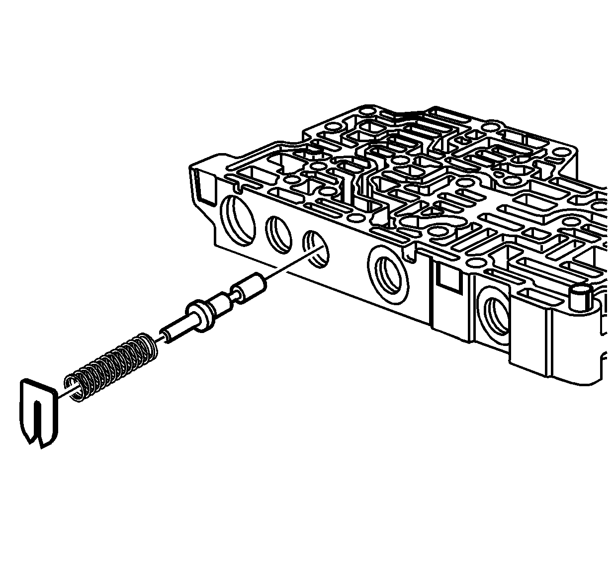
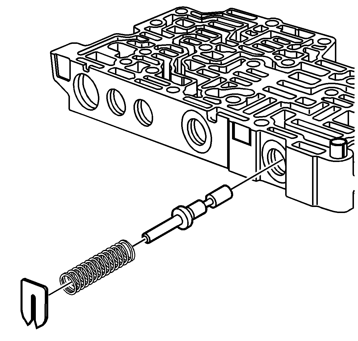
- Install the TCC control valve.
- Install the TCC control valve spring.
- Install the spring seat for the TCC control valve.
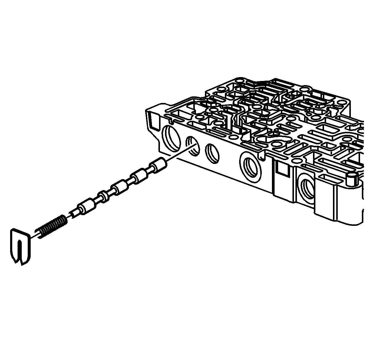
- Install the line limit valve.
- Install the line limit valve spring.
- Install the spring seat for the line limit valve.
- Install the actuator feed limit valve.
- Install the spring for the actuator feed limit valve.
- Install the spring seat for the actuator feed limit valve.
- Install the primary limit valve.
- Install the primary limit valve spring.
- Install the spring seat for the primary limit valve.
- Install the line 2 pressure regulator valve.
- Install the line 2 pressure regulator valve spring.
- Install a NEW bore plug - O-ring - seal on the bore plug for the line 2 pressure regulator valve.
- Install the bore plug for the line 2 pressure regulator valve.
- Install the bore plug retainer for the line 2 pressure regulator valve.
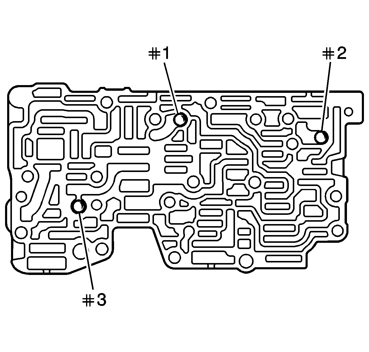
- Install the 3 ball check valves into the valve body assembly.
- Install a NEW fluid pump pressure screen assembly (203) on the spacer plate assembly.
- Install a NEW spacer plate assembly (204).
- Install the control solenoid valve assembly (201) on the valve body assembly (207).
- Install the wiring connector hole seal (200) for the control valve body cover.
- Install the manual valve (202) in the control solenoid valve assembly.
Important: Dirty solvent can deposit sediment that could damage the transmission.
| • | Porosity |
| • | Cracks |
| • | Damaged machined surfaces |
| • | Chips or debris |
| • | Interconnected passages |
| • | Damaged sealing surfaces |
| • | Worn or damaged valves |
| • | Broken, missing or damaged springs |
| • | Damaged bore plugs, spring seats or retainers |
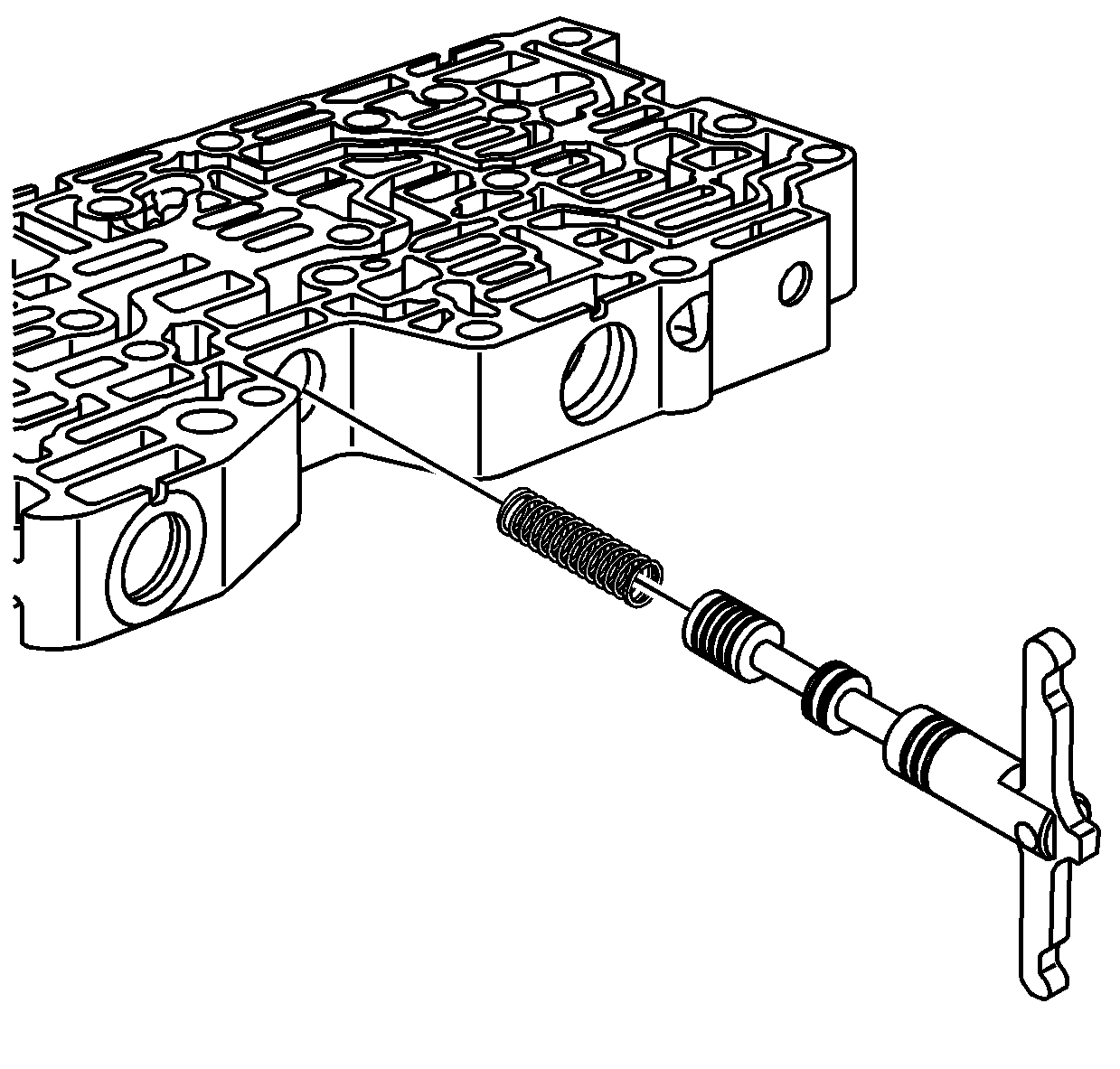
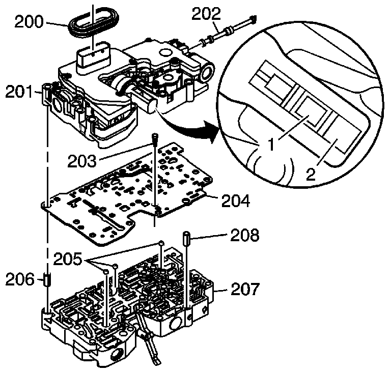
Important: Note the orientation of the variable ratio control valve lever assembly
into the ratio control motor.
• 1 - correct location • 2 - incorrect location
