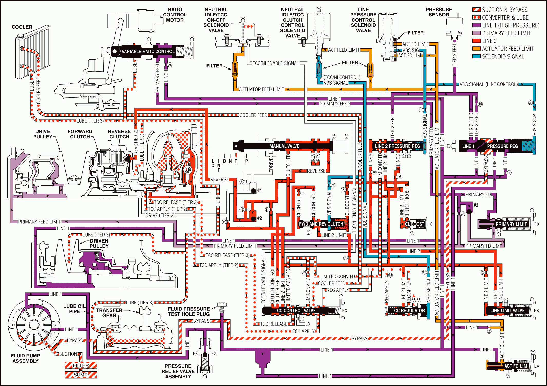
For 1990-2009 cars only
When the range selector lever is moved to the Reverse (R) position - from the Park position, the following changes occur in the transmission's hydraulic and electrical systems.
Reverse Clutch Applies
Manual Valve: With the manual valve in the reverse position, clutch feed pressure is directed into the reverse fluid circuit.#2 Ball Check Valve: Located in the control valve body assembly, the #2 ball check valve remains unseated and routes reverse fluid to the reverse clutch.
Reverse Clutch Assembly: Reverse clutch fluid is routed to the reverse clutch piston to apply the reverse clutch plates.
Pressure Regulation
Line Pressure Control Solenoid Valve: The line pressure control solenoid valve duty cycle is ramped up, increasing VBS signal - line control, fluid pressure.Line 2 Pressure Regulator Valve: Increased VBS signal fluid pressure, together with spring force, moves the line 2 pressure regulator valve against orificed line 2 fluid pressure to increase the amount of tier 2 feed fluid pressure that is regulated into the line 2 circuit.
Line Limit Valve: Increased line 2 fluid pressure is routed to the line limit valve where it is regulated against spring force into the line 2 limit fluid circuit, increasing line 2 limit fluid pressure.
Clutch Boost Valve: Increased line 2 limit fluid is routed to the clutch boost valve and moves the valve against spring force and enters the clutch boost fluid circuit.
Forward and Reverse Clutch Valve: Clutch boost fluid is routed to the forward and reverse clutch valve where it assists spring force and moves the valve against VBS signal and orificed clutch control fluid pressures. This allows increased line 2 limit fluid pressure to increase the amount of fluid pressure in the clutch control circuit.
TCC Control Valve: Increased clutch control fluid pressure passes through the TCC control valve and increases the pressure in the clutch feed circuit. This allows extra fluid pressure to enter the reverse circuit, at the manual valve, in order to provide additional force to apply the reverse clutch plates.
Ratio Control
Important: Remember that the function of an orifice is to control the flow rate of fluid and the rate of apply or release of a clutch or pulley
Ratio Control Motor and Variable Ratio Control Valve: The ratio control motor is activated by the TCM, in response to throttle position, and moves the variable ratio control valve against spring force. This allows line 1 fluid to be regulated into the primary feed circuit.Primary Limit Valve: Primary feed fluid is routed to the primary limit valve where it is regulated against spring force into the primary feed limit circuit.
#3 Ball Check Valve: Located in the control valve body assembly, primary feed fluid seats the #3 ball check valve and passes through orifice #24 into the primary feed limit circuit. This orifice helps to control variable drive pulley assembly apply.
Variable Drive Pulley Assembly Applied: Primary feed limit fluid enters the variable drive pulley assembly and acts on the variable drive pulley piston to control the variable drive ratio.
Reverse

