Removal Procedure
Tools Required
| • | J 45878 Combustible Gas Detector |
| • | J 45529 CNG Tank Sling |
| • | J 43133 CNG Tank Remover |
- Remove the tank cover. Refer to Fuel Tank Cover Replacement .
- Relieve the system pressure. Refer to Fuel Pressure Relief .
- Disconnect the negative battery cable.
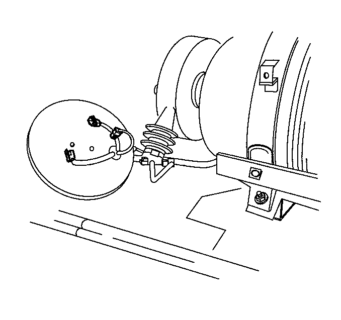
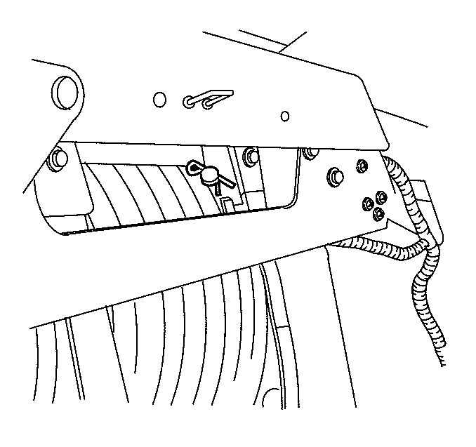
- Remove the tank vent boot cover nuts and the cover.
- Disconnect the 3 electrical connectors.
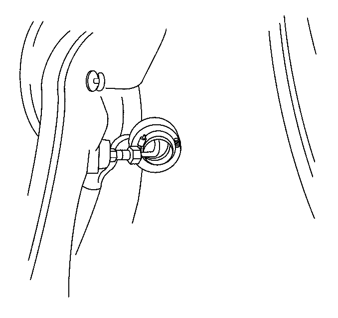
- Loosen the fill valve boot clamp and peel back the boot.
- Disconnect the fill line at the fill valve.
- Loosen the clamp at the tank vent boot and peel back the boot to expose the union.
- Disconnect the fill line at the union.
- Disconnect the fill line at the HPL.
- Disconnect the HPL to HPR fuel line at the HPL.
- Disconnect the Pressure Relief Device line at the HPL.
- Remove the trunk trim panel.
- Remove the cargo net, the cargo net knobs and the left wheelhouse carpet.
- Remove the fill line from the fill valve to the union. Refer to Fill Line Replacement - Fill Valve to Union .
- Lower the rear seat.
- Loosen the vent hose clamps at the tank valve boot and the HPR mounting ring.
- Pull up the boot and loosen the fuel line at the HPR.
- Remove the lines and the vent boot as an assembly.
- Remove the spare tire bracket.
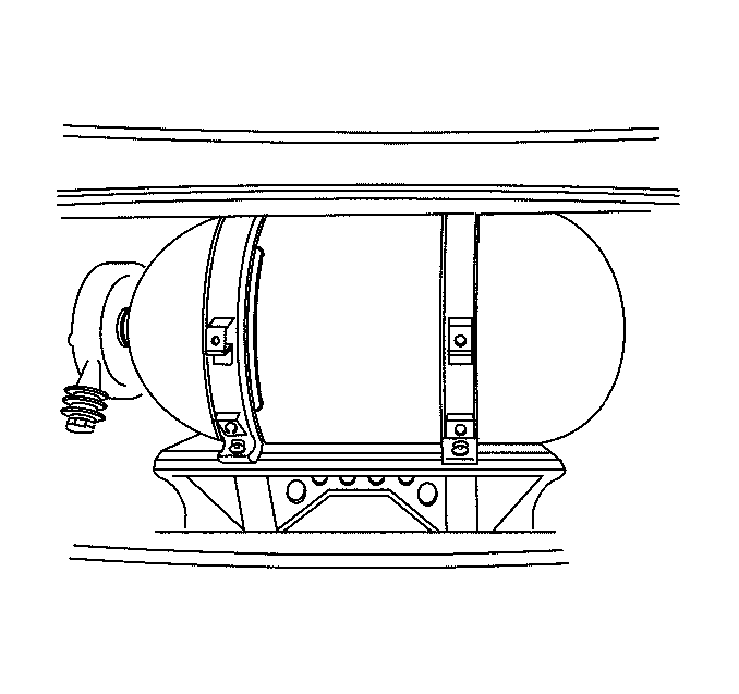
- Mark the tank in 2 places approximately 180 degrees apart for reference.
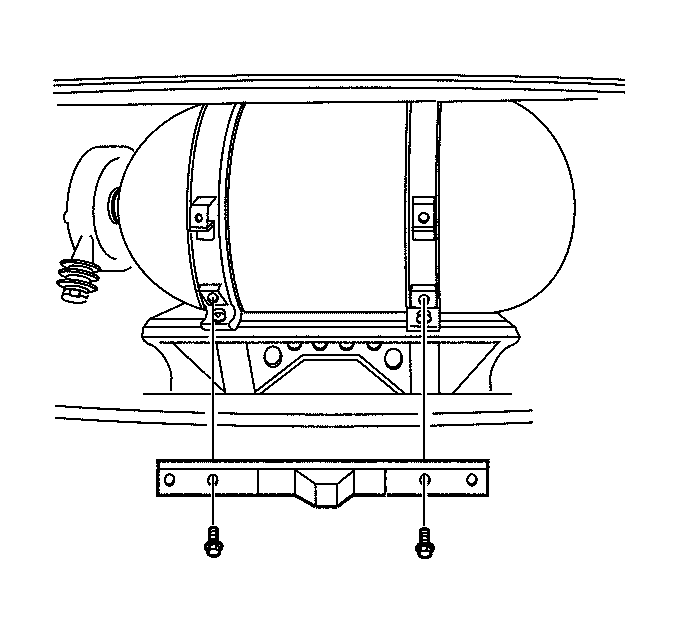
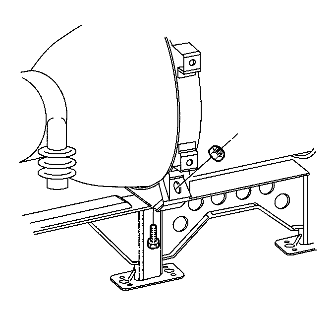
- Remove the tank strap nuts and the bolts. Discard the nuts and the bolts.
- Remove the clevis and the bridge pins.
- Remove the tank straps.
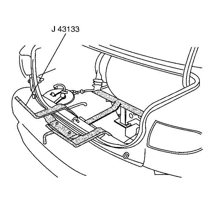
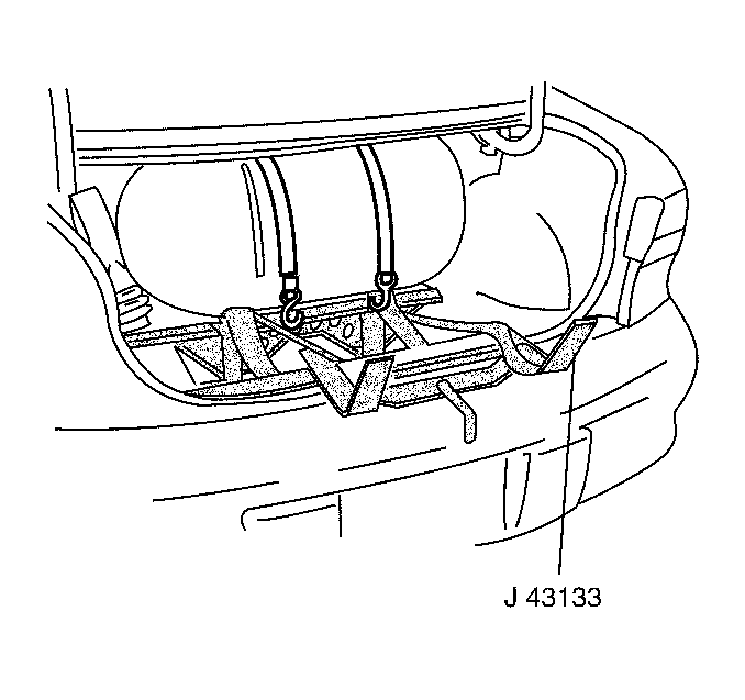
- Position the J 43133 into the tank strap bolt holes.
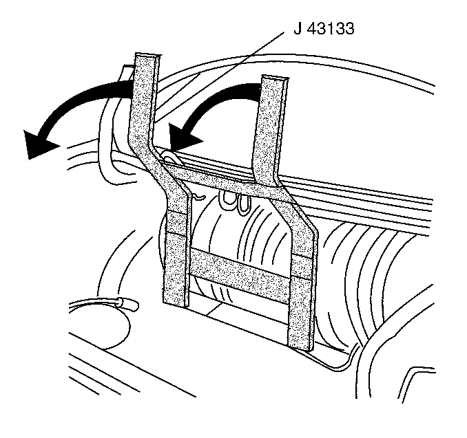
- Loop the J 43133 straps around the tank and secure the straps to the tool.
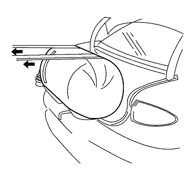
- Pull back the J 43133 in order to pull the tank free from the bracket.
- Pull back on the straps in order to roll the tank to the upper level of the J 43133 .
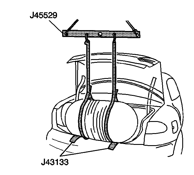
- Use a lifting device and the J 45529 in order to remove the tank from the vehicle.
- Remove the J 43133 from the vehicle.
Caution: Unless directed otherwise, the ignition and start switch must be in the OFF or LOCK position, and all electrical loads must be OFF before servicing any electrical component. Disconnect the negative battery cable to prevent an electrical spark should a tool or equipment come in contact with an exposed electrical terminal. Failure to follow these precautions may result in personal injury and/or damage to the vehicle or its components.
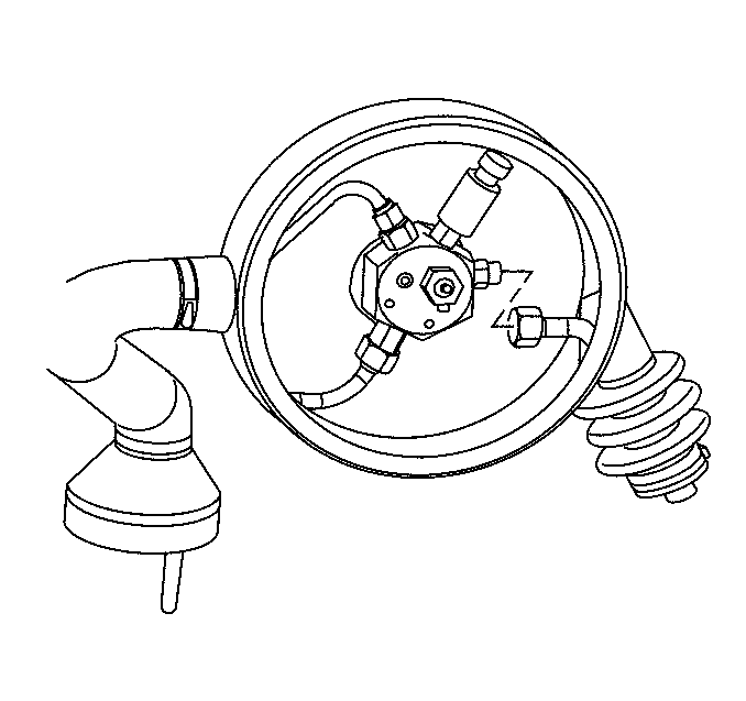
Disassembly Procedure
Important: Shipping regulations prohibit transporting a fuel tank containing CNG. Vent the fuel tank before shipping it.
If replacing the tank, remove the following components:
- The rubber isolators
- The fuel tank pressure (FTP) sensor (2)
- The fuel inlet fitting (3) from the tank valve
- The fuel outlet fitting (1) from the tank valve
- The HPL Pressure Relief Device line fitting (4) from the tank valve
- The vent boot
- Remove and discard the CNG Fuel Only label from the fill door.
- Remove and discard the Bi-fuel Information label from the underhood area.
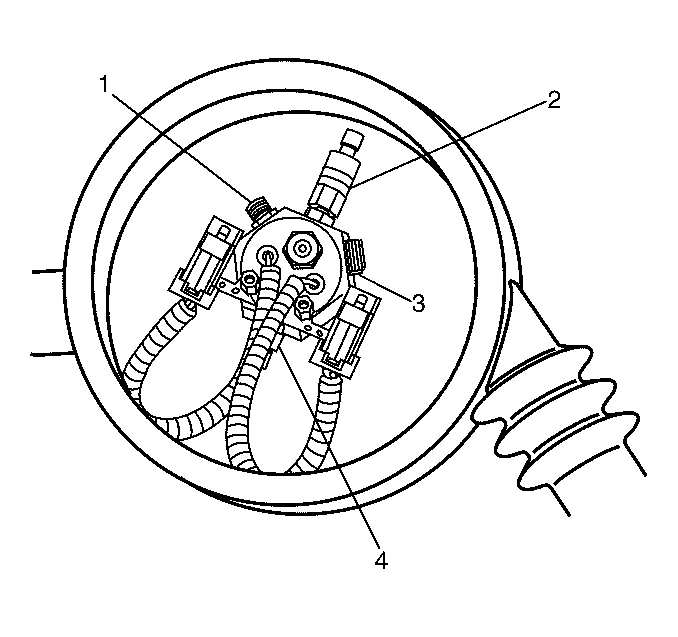
Assembly Procedure
If replacing the tank, install the following components:
- Install the vent boot.
- Install the fuel outlet fitting (1) to the tank valve using a new O-ring. Lubricate the new O-ring face seal with petroleum jelly or the equivalent.
- Install the fuel inlet fitting (3) to the tank valve using a new O-ring. Lubricate the new O-ring face seal with petroleum jelly or the equivalent.
- Install the FTP sensor (2) using a new O-ring face seal. Lubricate the new O-ring with petroleum jelly or the equivalent.
- Install the HPL Pressure Relief Device line fitting (4) in the tank valve.
- Install the new rubber isolators.
- Obtain a new CNG Fuel Only label and a new Bi-fuel Information label.
- Record the new tank service expiration date on each label.
- Install the new labels.
Notice: Use the correct fastener in the correct location. Replacement fasteners must be the correct part number for that application. Fasteners requiring replacement or fasteners requiring the use of thread locking compound or sealant are identified in the service procedure. Do not use paints, lubricants, or corrosion inhibitors on fasteners or fastener joint surfaces unless specified. These coatings affect fastener torque and joint clamping force and may damage the fastener. Use the correct tightening sequence and specifications when installing fasteners in order to avoid damage to parts and systems.

Tighten
Tighten the vent boot clamp to 2 N·m (18 lb ft).
Tighten
Tighten the fitting to 27 N·m (20 lb ft).
Tighten
Tighten the fitting to 48 N·m (35 lb ft).
Tighten
Tighten the FTP sensor to 27 N·m (20 lb ft).
Tighten
Tighten the fitting to 48 N·m (35 lb ft).
Installation Procedure
- Install the J 43133 into the tank strap bolt holes. The straps are not required for installation.
- Lower the tank onto the J 43133 using a lifting device and the J 45529 .
- Roll the tank to the proper position using the orientation marks.
- Raise the J 43133 and roll the tank into position in the tank cradle.
- Verify the alignment of the HPL inlet fitting. The fitting should be at the 3 o'clock position.
- The HPL should be 26.7 cm (10½ in) from the left edge of the left tank strap.
- Remove the J 43133 from the bracket.
- Install the tank straps.
- Install the tank strap bridge pins and the clevis pins.
- Install the new tank strap bolts and the new nuts.
- Install the Pressure Relief Device line and the HPL to HPR lines and the vent hose as an assembly.
- Connect the Pressure Relief Device and the HPL to HPR lines using new O-ring face seals. Lubricate the O-rings with petroleum jelly or the equivalent.
- Install the fill valve to union fill line using new O-ring face seals. Lubricate the O-rings with petroleum jelly or the equivalent.
- Install the union to HPL fill line using new O-ring face seals. Lubricate the O-rings with petroleum jelly or the equivalent.
- Connect the electrical connectors and the HPL power connector.
- Connect the negative battery cables.
- Fill the CNG fuel system.
- Start the engine. Inspect for CNG fuel leaks at each serviced fitting using the J 45878 .
- Position the 4 hose clamps at the vent boot, the vent hose and the fill valve boot.
- Install the vent boot cover and the cover nuts.
- Install the left side trunk carpet.
- Install the cargo net knobs and the cargo net.
- Install the trunk trim.
- Install the spare tire bracket and the spare tire bracket bolts.
- Install the tank cover. Refer to Fuel Tank Cover Replacement .


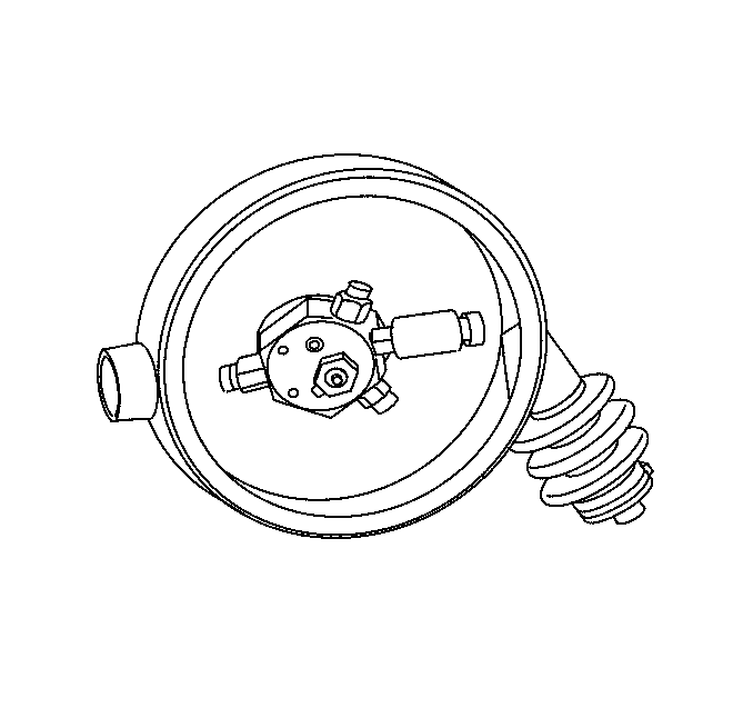
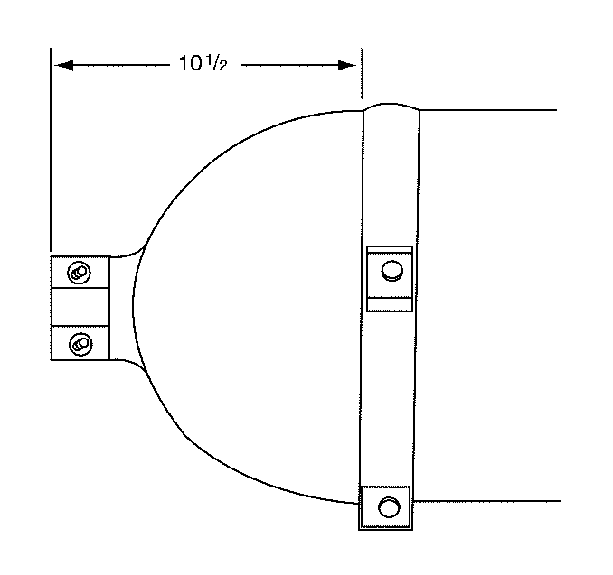

Notice: Use the correct fastener in the correct location. Replacement fasteners must be the correct part number for that application. Fasteners requiring replacement or fasteners requiring the use of thread locking compound or sealant are identified in the service procedure. Do not use paints, lubricants, or corrosion inhibitors on fasteners or fastener joint surfaces unless specified. These coatings affect fastener torque and joint clamping force and may damage the fastener. Use the correct tightening sequence and specifications when installing fasteners in order to avoid damage to parts and systems.

Tighten
Tighten the tank strap nuts to 47 N·m (35 lb ft).
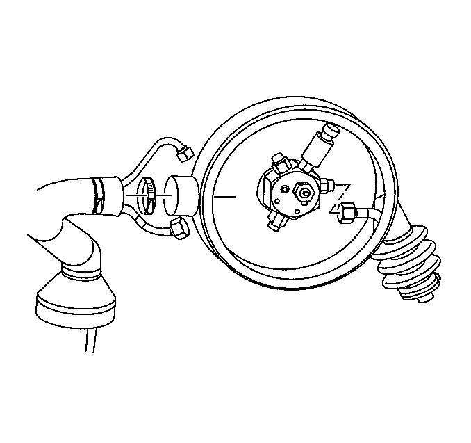
Tighten
| • | Tighten the Pressure Relief Device line fitting to 37 N·m (27 lb ft). |
| • | Tighten the HPL to HPR fuel line fittings to 24 N·m (18 lb ft). |
Tighten
Tighten the fill line fittings to 37 N·m (27 lb ft).
Tighten
Tighten the fill line fittings to 37 N·m (27 lb ft).
Tighten
Tighten the bolt to 15 N·m (11 lb ft).
Tighten
Tighten the four hose clamps to 2 N·m (18 lb in).
Tighten
Tighten the vent boot cover nuts to 6 N·m (54 lb in).
Tighten
Tighten the spare tire bracket bolts to 27 N·m (20 lb ft).
