Communication Interface Module Replacement for Generic Unit Repair 2005
Removal Procedure
Important: The communication interface module has a specific set of unique numbers that tie the module to each vehicle. These numbers, the 10-digit station identification and the 11-digit electronic serial number, are used by the National Cellular Network and OnStar to identify the specific vehicle. Because these numbers are tied to the vehicle identification number of the vehicle, you must never exchange these parts with those of another vehicle.
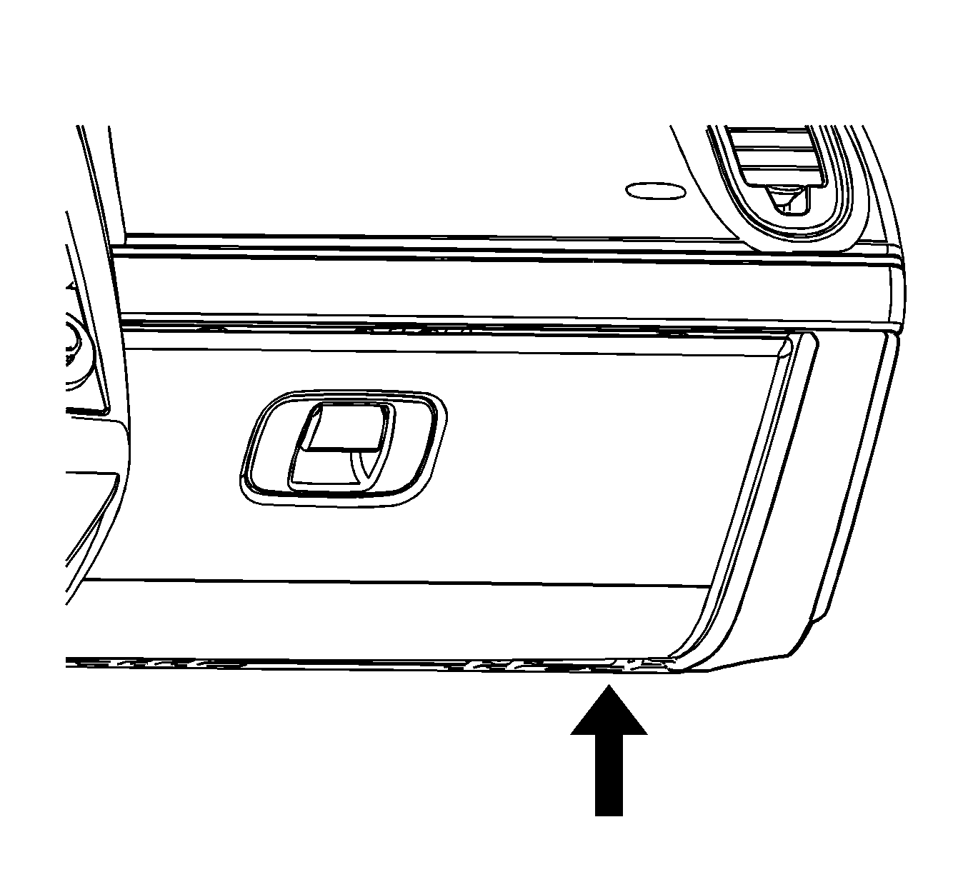
- Remove the right closeout panel. Refer to Instrument Panel Insulator Panel Replacement - Right Side in Instrument Panel, Gages and Console.
- Release the Glove Box opening stop tabs to allow glove box to rotate fully open for access to fasteners.
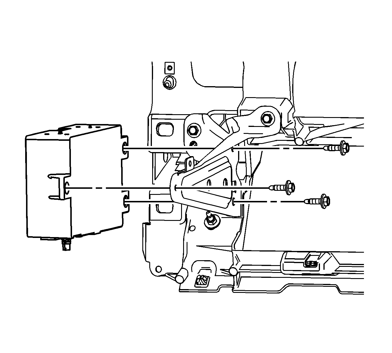
- Disconnect the communication interface module wire harness and antenna connectors.
- Remove the communication interface module bolts.
- Remove the communication interface module.
Installation Procedure
- Install the communication interface module.
- Tighten the communication interface module bolts.
- Connect the communication interface module wire harness and antenna connectors.
- Install the right closeout panel. Refer to Instrument Panel Insulator Panel Replacement - Right Side in Instrument Panel, Gages and Console.
- Reconfigure the OnStar system. Refer to Control Module References in Computer/Integrating Systems.
Notice: Refer to Fastener Notice in the Preface section.
Tighten
Tighten the bolts to 10 N·m (89 lb in).
Important: After replacing the communication interface module, you must reconfigure the OnStar system. Failure to reconfigure the system will result in an additional customer visit or repair. In addition, pressing and holding the white dot button on the keypad will NOT reset the OnStar system. This action will cause a DTC to set.
