|
| ||||||||||||||
|---|---|---|---|---|---|---|---|---|---|---|---|---|---|---|---|
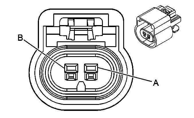
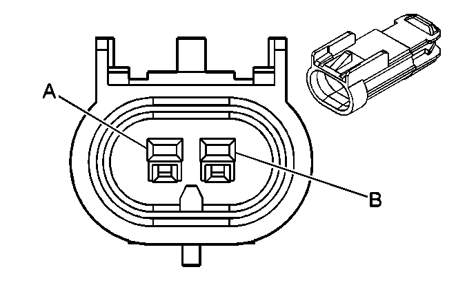
Connector Part Information |
| Connector Part Information |
| ||||||||||||
Pin | Wire Color | Circuit No. | Function | Pin | Wire Color | Circuit No. | Function | ||||||||
A | L-BU | 830 | Left Front Wheel Speed Sensor Supply Voltage | A | L-BU | 830 | Left Front Wheel Speed Sensor Supply Voltage | ||||||||
B | YE | 873 | Left Front Wheel Speed Sensor Signal | B | YE | 873 | Left Front Wheel Speed Sensor Signal | ||||||||

|

| ||||||||||||||
|---|---|---|---|---|---|---|---|---|---|---|---|---|---|---|---|
Connector Part Information |
| Connector Part Information |
| ||||||||||||
Pin | Wire Color | Circuit No. | Function | Pin | Wire Color | Circuit No. | Function | ||||||||
A | L-BU | 872 | Right Front Wheel Speed Sensor Supply Voltage | A | D-GN | 872 | Right Front Wheel Speed Sensor Supply Voltage | ||||||||
B | YE | 833 | Right Front Wheel Speed Sensor Signal | B | TN | 833 | Right Front Wheel Speed Sensor Signal | ||||||||
|
| ||||||||||||||
|---|---|---|---|---|---|---|---|---|---|---|---|---|---|---|---|
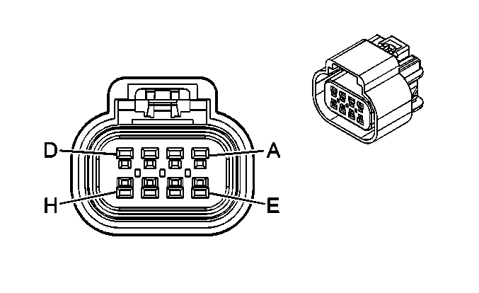
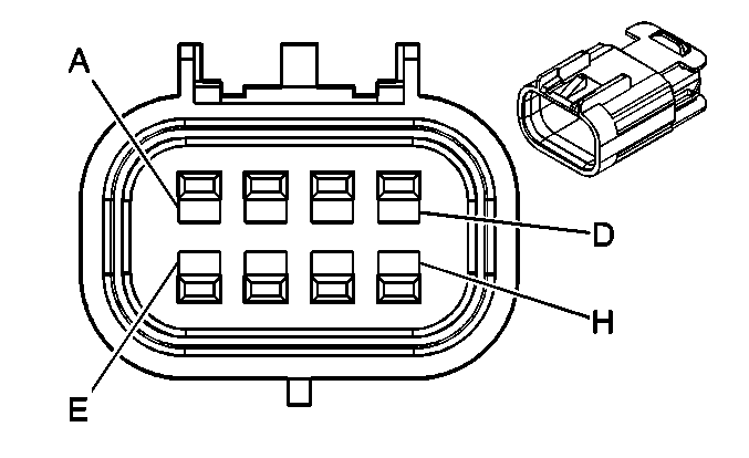
Connector Part Information |
| Connector Part Information |
| ||||||||||||
Pin | Wire Color | Circuit No. | Function | Pin | Wire Color | Circuit No. | Function | ||||||||
A | WH | 17 | Stop Lamp Switch Signal | A | WH | 17 | Stop Lamp Switch Signal | ||||||||
B | -- | -- | Not Used | B | -- | -- | Not Used | ||||||||
C | BN | 1271 | Low Reference | C | BN | 1271 | Low Reference | ||||||||
D | WH/BK | 1164 | 5-Volt Reference | D | WH/BK | 1164 | 5-Volt Reference | ||||||||
E | D-BU | 1161 | APP Sensor 1 Signal | E | D-BU | 1161 | APP Sensor 1 Signal | ||||||||
F | PU | 1272 | Low Reference | F | PU | 1272 | Low Reference | ||||||||
G | TN | 1274 | 5-Volt Reference | G | TN | 1274 | 5-Volt Reference | ||||||||
H | L-BU | 1162 | APP Sensor 2 Signal | H | L-BU | 1162 | APP Sensor 2 Signal | ||||||||
|
| ||||||||||||||
|---|---|---|---|---|---|---|---|---|---|---|---|---|---|---|---|
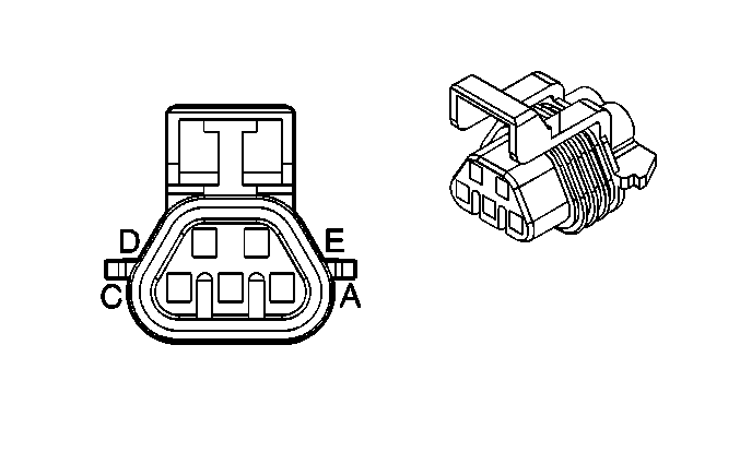
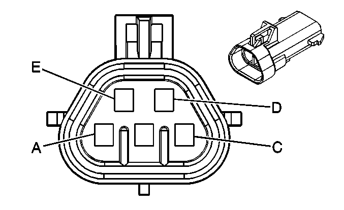
Connector Part Information |
| Connector Part Information |
| ||||||||||||
Pin | Wire Color | Circuit No. | Function | Pin | Wire Color | Circuit No. | Function | ||||||||
A | BK | 150 | Ground | A | BK | 150 | Ground | ||||||||
B | YE | 712 | Left Headlamp Low Beam Supply Voltage | B | YE | 712 | Left Headlamp Low Beam Supply Voltage | ||||||||
C | D-GN/WH | 711 | Left Headlamp High Beam Supply Voltage | C | L-GN | 711 | Left Headlamp High Beam Supply Voltage | ||||||||
D | L-BU/WH | 1314 | Left DRL/Turn Supply Voltage | D | PU | 1314 | Left DRL/Turn Supply Voltage | ||||||||
E | BN | 9 | Park Lamp Supply Voltage | E | BN | 9 | Park Lamp Supply Voltage | ||||||||

|

| ||||||||||||||
|---|---|---|---|---|---|---|---|---|---|---|---|---|---|---|---|
Connector Part Information |
| Connector Part Information |
| ||||||||||||
Pin | Wire Color | Circuit No. | Function | Pin | Wire Color | Circuit No. | Function | ||||||||
A | BK | 250 | Ground | A | BK | 250 | Ground | ||||||||
B | TN/WH | 312 | Right Headlamp Low Beam Supply Voltage | B | TN/WH | 312 | Right Headlamp Low Beam Supply Voltage | ||||||||
C | L-GN/BK | 311 | Right Headlamp High Beam Supply Voltage | C | L-GN | 311 | Right Headlamp High Beam Supply Voltage | ||||||||
D | D-BU/WH | 1315 | Right DRL/Turn Supply Voltage | D | PU | 1315 | Right DRL/Turn Supply Voltage | ||||||||
E | BN | 9 | Park Lamp Supply Voltage | E | BN | 9 | Park Lamp Supply Voltage | ||||||||
|
| ||||||||||||||
|---|---|---|---|---|---|---|---|---|---|---|---|---|---|---|---|
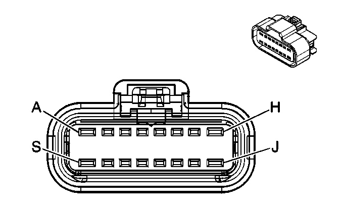
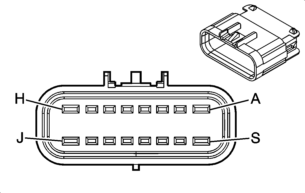
Connector Part Information |
| Connector Part Information |
| ||||||||||||
Pin | Wire Color | Circuit No. | Function | Pin | Wire Color | Circuit No. | Function | ||||||||
A | PK | 839 | Ignition 1 Voltage | A | PK | 639 | Ignition 1 Voltage | ||||||||
B | YE | 410 | ECT Sensor Signal | B | YE | 410 | ECT Sensor Signal | ||||||||
C | TN | 1744 | Fuel Injector 1 Control | C | BK | 1744 | Fuel Injector 1 Control | ||||||||
D | L-GN/BK | 1745 | Fuel Injector 2 Control | D | L-GN/BK | 1745 | Fuel Injector 2 Control | ||||||||
E | PK/BK | 1746 | Fuel Injector 3 Control | E | PK/BK | 1746 | Fuel Injector 3 Control | ||||||||
F | L-BU/BK | 844 | Fuel Injector 4 Control | F | L-BU/BK | 844 | Fuel Injector 4 Control | ||||||||
G | TN/WH | 845 | Fuel Injector 5 Control | G | BK/WH | 845 | Fuel Injector 5 Control | ||||||||
H | YE/BK | 846 | Fuel Injector 6 Control | H | YE/BK | 846 | Fuel Injector 6 Control | ||||||||
J | -- | -- | Not Used | J | -- | -- | Not Used | ||||||||
K | GY | 2704 | 5-Volt Reference | K | GY | 2704 | 5-Volt Reference | ||||||||
L | OG/BK | 469 | Low Reference | L | OG/BK | 469 | Low Reference | ||||||||
M | L-GN | 432 | MAP Sensor Signal | M | L-GN | 432 | MAP Sensor Signal | ||||||||
N | OG | 631 | 12-Volt Reference | N | RD/WH | 812 | 12-Volt Reference | ||||||||
P | PK/BK | 632 | Low Reference | P | BK | 407 | Low Reference | ||||||||
R | BN/WH | 633 | CMP Sensor Signal | R | BN/WH | 633 | CMP Sensor Signal | ||||||||
S | -- | -- | Not Used | S | -- | -- | Not Used | ||||||||
|
| ||||||||||||||
|---|---|---|---|---|---|---|---|---|---|---|---|---|---|---|---|
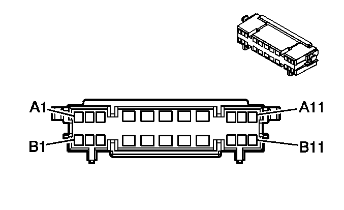
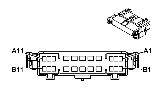
Connector Part Information |
| Connector Part Information |
| ||||||||||||
Pin | Wire Color | Circuit No. | Function | Pin | Wire Color | Circuit No. | Function | ||||||||
A1 | L-BU | 1162 | APP Sensor 2 Signal | A1 | L-BU | 1162 | APP Sensor 2 Signal | ||||||||
A2 | TN | 1274 | 5-Volt Reference | A2 | TN | 1274 | 5-Volt Reference | ||||||||
A3 | PU | 1272 | Low Reference | A3 | PU | 1272 | Low Reference | ||||||||
A4 | TN/BK | 2500 | High Speed GMLAN Serial Data Bus + | A4 | TN/BK | 2500 | High Speed GMLAN Serial Data Bus + | ||||||||
A5 | -- | -- | Not Used | A5 | PPL | 1807 | Class 2 Serial Data | ||||||||
A6 | PK/WH | 1970 | Headlamp Low Beam Relay Control | A6 | PK/WH | 1970 | Headlamp Low Beam Relay Control | ||||||||
PK/WH | 1970 | Headlamp Low Beam Relay Control | |||||||||||||
A7 | BN/WH | 2517 | Keypad Red LED Signal (UE1) | A7 | BN/WH | 2517 | Keypad Red LED Signal (UE1) | ||||||||
A8 | L-GN/BK | 2515 | Keypad Supply Voltage (UE1) | A8 | L-GN/BK | 2515 | Keypad Supply Voltage (UE1) | ||||||||
A9 | GY | 655 | Cellular Microphone Signal (UE1) | A9 | GY | 655 | Cellular Microphone Signal (UE1) | ||||||||
A10 | -- | -- | Not Used | A10 | -- | -- | Not Used | ||||||||
A11 | BN/WH | 419 | MIL Control | A11 | BN/WH | 419 | MIL Control | ||||||||
B1 | D-BU | 1161 | APP Sensor 1 Signal | B1 | D-BU | 1161 | APP Sensor 1 Signal | ||||||||
B2 | WH/BK | 1164 | 5-Volt Reference | B2 | WH/BK | 1164 | 5-Volt Reference | ||||||||
B3 | BN | 1271 | Low Reference | B3 | BN | 1271 | Low Reference | ||||||||
B4 | TN | 2501 | High Speed GMLAN Serial Data Bus - | B4 | TN | 2501 | High Speed GMLAN Serial Data Bus - | ||||||||
B5 | PK | 5165 | Antenna 14-Volt Switched Supply Voltage | B5 | PK | 5165 | Antenna 14-Volt Switched Supply Voltage | ||||||||
PK | 5165 | Antenna 14-Volt Switched Supply Voltage (U85) | |||||||||||||
B6 | -- | -- | Not Used | B10 | -- | -- | Not Used | ||||||||
B7 | YE/BK | 2516 | Keypad Green LED Signal (UE1) | B7 | YE/BK | 2516 | Keypad Green LED Signal (UE1) | ||||||||
B8 | D-GN/WH | 2514 | Keypad Signal (UE1) | B8 | D-GN/WH | 2514 | Keypad Signal (UE1) | ||||||||
B9 | BARE | 1489 | Drain Wire (UE1) | B9 | BARE | 1489 | Drain Wire (UE1) | ||||||||
B10 | -- | -- | Not Used | B10 | -- | -- | Not Used | ||||||||
B11 | GY | 91 | Windshield Wiper Switch Signal 2 | B11 | GY | 91 | Windshield Wiper Switch Signal 2 | ||||||||

|

| ||||||||||||||
|---|---|---|---|---|---|---|---|---|---|---|---|---|---|---|---|
Connector Part Information |
| Connector Part Information |
| ||||||||||||
Pin | Wire Color | Circuit No. | Function | Pin | Wire Color | Circuit No. | Function | ||||||||
A1 | TN | 201 | Left Front Speaker Output (+) (UZ6) | A1 | TN | 201 | Left Front Speaker Output (+) (UZ6) | ||||||||
A1 | TN | 511 | Left Front Low Level Audio Signal (+) (U85) | A1 | TN | 512 | Left Front Low Level Audio Signal (+) (U85) | ||||||||
A2 | L-GN | 200 | Right Front Speaker Output (+) (UZ6) | A2 | L-GN | 200 | Right Front Speaker Output (+) (UZ6) | ||||||||
A2 | D-GN | 512 | Right Front Low Level Audio Signal (+) (U85) | A2 | D-GN | 512 | Right Front Low Level Audio Signal (+) (U85) | ||||||||
A3 | -- | -- | Not Used | A3 | -- | -- | Not Used | ||||||||
A4 | TN/WH | 372 | Audio Common (U2K) | A4 | TN/WH | 372 | Audio Common (U2K) | ||||||||
A5 | OG | 5748 | Amplifier Mute (U85) | A5 | OG | 5748 | Amplifier Mute (U85) | ||||||||
A6-A9 | -- | -- | Not Used | A6-A9 | -- | -- | Not Used | ||||||||
A10 | D-BU | 46 | Right Rear Speaker Output (+) (UZ6) | A10 | D-BU | 46 | Right Rear Speaker Output (+) (UZ6) | ||||||||
A10 | D-BU | 546 | Right Rear Low Level Audio Signal (+) (U85) | A10 | D-BU | 546 | Right Rear Low Level Audio Signal (+) (U85) | ||||||||
A11 | BN | 199 | Left Rear Speaker Output (+) (UZ6) | A11 | BN | 199 | Left Rear Speaker Output (+) (UZ6) | ||||||||
A11 | BN/WH | 599 | Left Rear Low Level Audio Signal (+) (U85) | A11 | BN/WH | 599 | Left Rear Low Level Audio Signal (+) (U85) | ||||||||
B1 | GY | 118 | Left Front Speaker Output (-) (UZ6) | B1 | GY | 118 | Left Front Speaker Output (-) (UZ6) | ||||||||
B1 | D-GN | 1947 | Left Front Low Level Audio Signal (-) (U85) | B1 | GY | 118 | Left Front Low Level Audio Signal (-) (U85) | ||||||||
B2 | D-GN | 117 | Right Front Speaker Output (-) (UZ6) | B2 | D-GN | 117 | Right Front Speaker Output (-) (UZ6) | ||||||||
B2 | L-GN | 1948 | Right Front Low Level Audio Signal (-) (U85) | B2 | L-GN/BK | 1948 | Right Front Low Level Audio Signal (-) (U85) | ||||||||
B3 | -- | -- | Not Used | B3 | -- | -- | Not Used | ||||||||
B4 | BARE | 814 | Drain Wire (U2K) | B4 | BARE | 814 | Drain Wire (U2K) | ||||||||
B5 | BN/WH | 367 | Left Audio Signal (+) (U2K) | B5 | BN/WH | 367 | Left Audio Signal (+) (U2K) | ||||||||
B6 | D-GN/WH | 368 | Right Audio Signal (+) (U2K) | B6 | D-GN/WH | 368 | Right Audio Signal (+) (U2K) | ||||||||
B7-B9 | -- | -- | Not Used | B7-B9 | -- | -- | Not Used | ||||||||
B10 | L-BU | 115 | Right Rear Speaker Output (-) (UZ6) | B10 | L-BU | 115 | Right Rear Speaker Output (-) (UZ6) | ||||||||
B10 | TN | 1946 | Right Rear Low Level Audio Signal (-) (U85) | B10 | TN | 1946 | Right Rear Low Level Audio Signal (-) (U85) | ||||||||
B11 | YE | 116 | Left Rear Speaker Output (-) (UZ6) | B11 | YE | 116 | Left Rear Speaker Output (-) (UZ6) | ||||||||
B11 | BN | 1999 | Left Rear Low Level Audio Signal (-) (U85) | B11 | BN | 1999 | Left Rear Low Level Audio Signal (-) (U85) | ||||||||
|
| ||||||||||||||
|---|---|---|---|---|---|---|---|---|---|---|---|---|---|---|---|
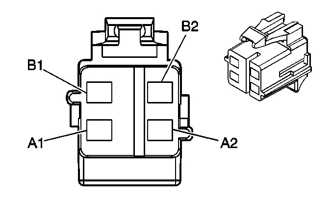
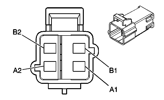
Connector Part Information |
| Connector Part Information |
| ||||||||||||
Pin | Wire Color | Circuit No. | Function | Pin | Wire Color | Circuit No. | Function | ||||||||
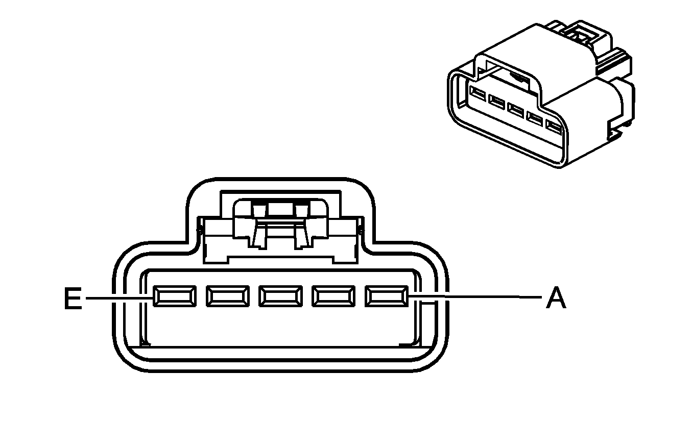
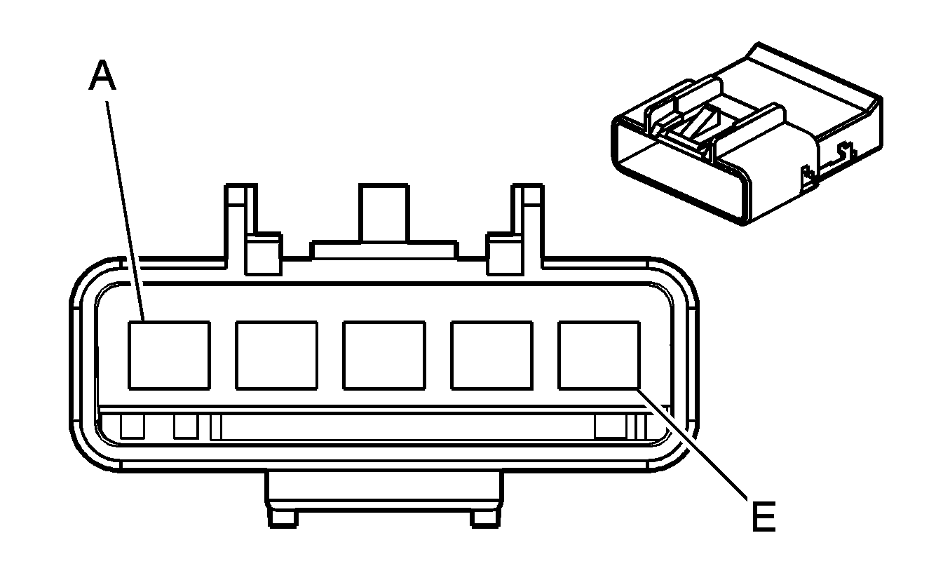
A1 | TN | 3021 | Steering Wheel Module - Stage 1 - High Control | A1 | TN | 3021 | Steering Wheel Module - Stage 1 - High Control | ||||||||
A2 | BN | 3020 | Steering Wheel Module - Stage 1 - Low Control | A2 | BN | 3020 | Steering Wheel Module - Stage 1 - Low Control | ||||||||
B1 | WH | 3023 | Steering Wheel Module - Stage 2 - High Control | B1 | WH | 3023 | Steering Wheel Module - Stage 2 - High Control | ||||||||
B2 | PK | 3022 | Steering Wheel Module - Stage 2 - Low Control | B2 | PK | 3022 | Steering Wheel Module - Stage 2 - Low Control | ||||||||
|
| ||||||||||||||
|---|---|---|---|---|---|---|---|---|---|---|---|---|---|---|---|
Connector Part Information |
| Connector Part Information |
| ||||||||||||
Pin | Wire Color | Circuit No. | Function | Pin | Wire Color | Circuit No. | Function | ||||||||
A | GY | 8 | Instrument Panel Lamp Supply Voltage (NW7/NW9) | A | GY | 8 | Instrument Panel Lamp Supply Voltage (NW7/NW9) | ||||||||
B | BN/WH | 1571 | Traction Control Switch Signal (NW7/NW9) | B | BN/WH | 1571 | Traction Control Switch Signal (NW7/NW9) | ||||||||
C | BK | 1050 | Ground (NW7/NW9) | C | BK | 1050 | Ground (NW7/NW9) | ||||||||
D | RD/WH | 40 | Battery Positive Voltage | D | RD/WH | 40 | Battery Positive Voltage | ||||||||
RD/WH | 40 | Battery Positive Voltage | |||||||||||||
E | BK | 1150 | Ground | E | BK | 1150 | Ground | ||||||||
BK | 1150 | Ground | |||||||||||||

|

| ||||||||||||||
|---|---|---|---|---|---|---|---|---|---|---|---|---|---|---|---|
Connector Part Information |
| Connector Part Information |
| ||||||||||||
Pin | Wire Color | Circuit No. | Function | Pin | Wire Color | Circuit No. | Function | ||||||||
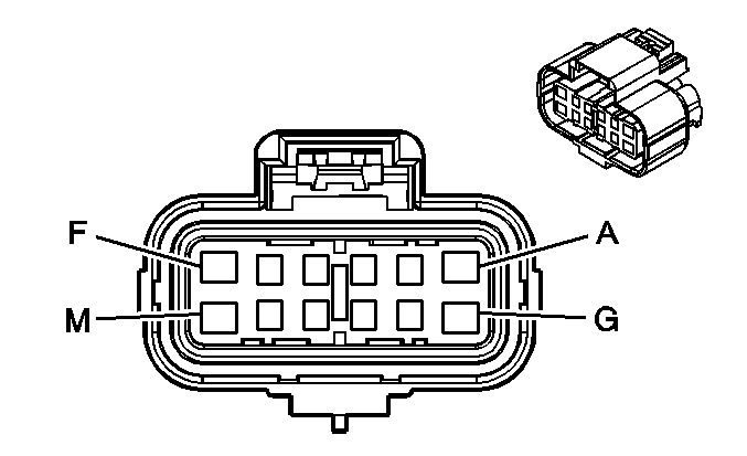
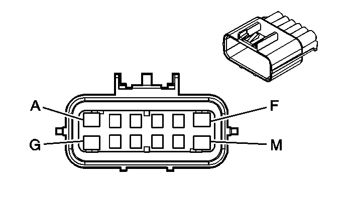
A1 | YE | 3025 | I/P Module - Stage 1 - High Control | A1 | YE | 3025 | I/P Module - Stage 1 - High Control | ||||||||
A2 | OG | 3024 | I/P Module - Stage 1 - Low Control | A2 | OG | 3024 | I/P Module - Stage 1 - Low Control | ||||||||
B1 | GY | 3027 | I/P Module - Stage 2 - High Control | B1 | GY | 3027 | I/P Module - Stage 2 - High Control | ||||||||
B2 | PU | 3026 | I/P Module - Stage 2 - Low Control | B2 | PU | 3026 | I/P Module - Stage 2 - Low Control | ||||||||
|
| ||||||||||||||
|---|---|---|---|---|---|---|---|---|---|---|---|---|---|---|---|
Connector Part Information |
| Connector Part Information |
| ||||||||||||
Pin | Wire Color | Circuit No. | Function | Pin | Wire Color | Circuit No. | Function | ||||||||
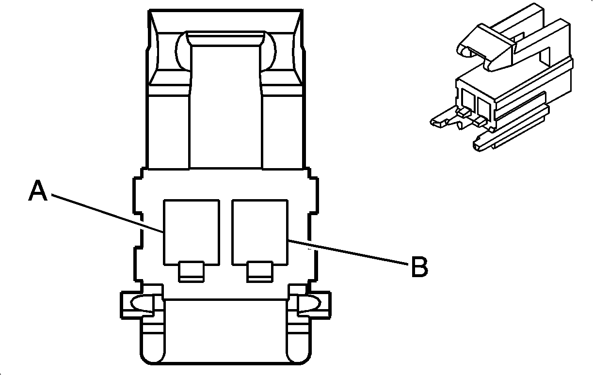
A | RD/BK | 1242 | Battery Positive Voltage (AG1/ASN) | A | RD/BK | 1242 | Battery Positive Voltage (AG1/ASN) | ||||||||
B | D-GN | 5016 | Seat Belt Switch - Left - Signal | B | D-GN | 5016 | Seat Belt Switch - Left - Signal | ||||||||
C-E | -- | -- | Not Used | C-E | -- | -- | Not Used | ||||||||
F | BK | 1150 | Ground (AG1/ASN) | F | BK | 1150 | Ground (AG1/ASN) | ||||||||
BK | 1150 | Ground (ASN) | |||||||||||||
G | PK | 5057 | Seat Position Sensor - Low Reference | G | PK | 5057 | Seat Position Sensor - Low Reference | ||||||||
H | YE | 243 | Accessory Voltage (KA1) | H | YE | 243 | Accessory Voltage (KA1) | ||||||||
J | RD/WH | 1140 | Battery Positive Voltage (KA1) | J | RD/WH | 1140 | Battery Positive Voltage (KA1) | ||||||||
K | GY | 8 | Instrument Panel Lamp Supply Voltage (KA1) | K | GY | 8 | Instrument Panel Lamp Supply Voltage (KA1) | ||||||||
L | -- | -- | Not Used | L | -- | -- | Not Used | ||||||||
M | BK | 1150 | Ground (KA1) | M | BK | 1150 | Ground (KA1) | ||||||||
BK | 1150 | Ground (KA1) | |||||||||||||
|
| ||||||||||||||
|---|---|---|---|---|---|---|---|---|---|---|---|---|---|---|---|
Connector Part Information |
| Connector Part Information |
| ||||||||||||
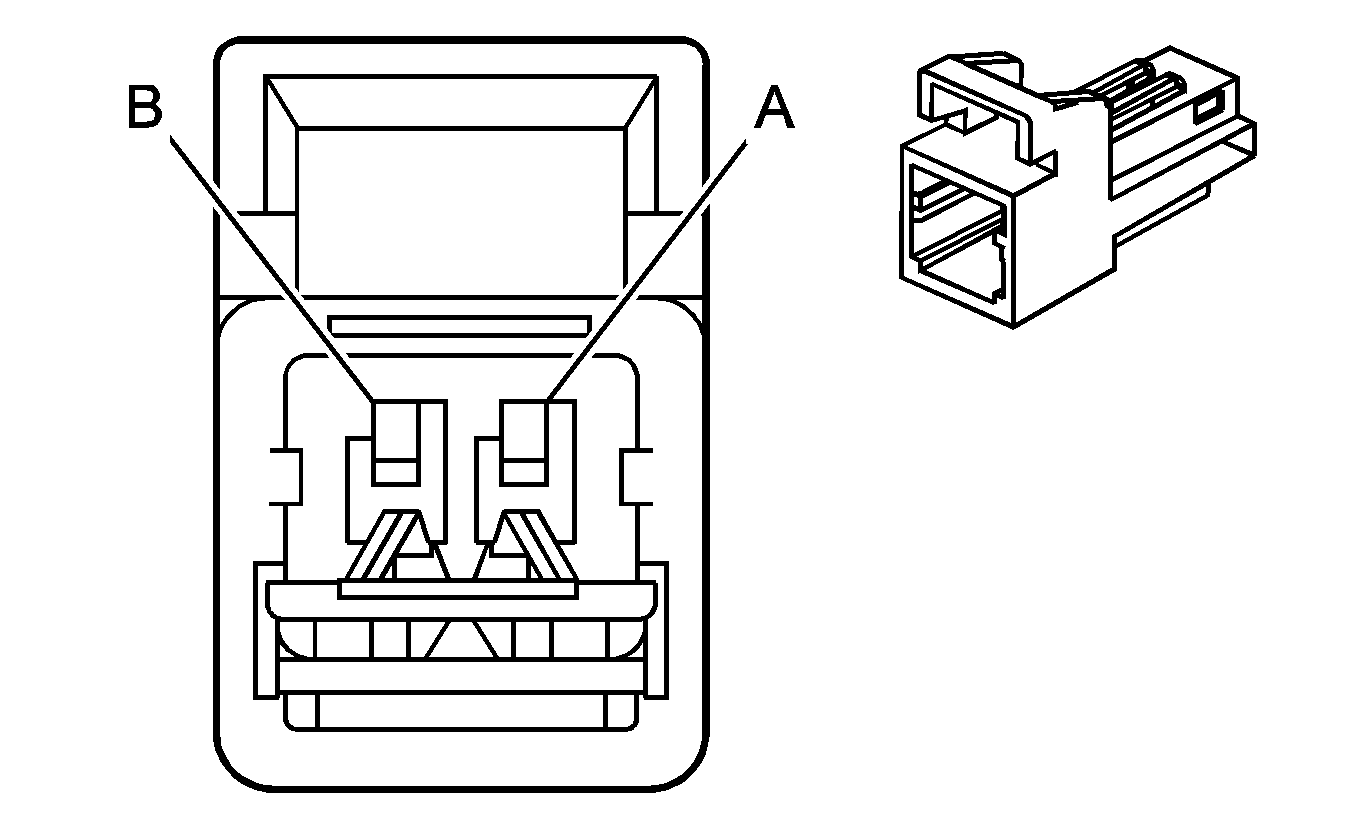
Pin | Wire Color | Circuit No. | Function | Pin | Wire Color | Circuit No. | Function | ||||||||
A | L-GN | 2136 | Side Impact Module - RF - Low Control | A | WH/BK | 2136 | Side Impact Module - RF - Low Control | ||||||||
B | TN/WH | 2135 | Side Impact Module - RF - High Control | B | TN/WH | 2135 | Side Impact Module - RF - High Control | ||||||||

|

| ||||||||||||||
|---|---|---|---|---|---|---|---|---|---|---|---|---|---|---|---|
Connector Part Information |
| Connector Part Information |
| ||||||||||||
Pin | Wire Color | Circuit No. | Function | Pin | Wire Color | Circuit No. | Function | ||||||||
A | YE/BK | 2138 | Side Impact Module - LF- Low Control | A | YE/BK | 2138 | Side Impact Module - LF- Low Control | ||||||||
B | BN | 2137 | Side Impact Module - LF - High Control | B | D-GN/WH | 2137 | Side Impact Module - LF - High Control | ||||||||

|

| ||||||||||||||
|---|---|---|---|---|---|---|---|---|---|---|---|---|---|---|---|
Connector Part Information |
| Connector Part Information |
| ||||||||||||
Pin | Wire Color | Circuit No. | Function | Pin | Wire Color | Circuit No. | Function | ||||||||
A | OG/BK | 2119 | Seat Belt Pretensioner - Left - Low Control | A | OG/BK | 2119 | Seat Belt Pretensioner - Left - Low Control | ||||||||
B | TN/WH | 2118 | Seat Belt Pretensioner - Left - High Control | B | TN/WH | 2118 | Seat Belt Pretensioner - Left - High Control | ||||||||

|

| ||||||||||||||
|---|---|---|---|---|---|---|---|---|---|---|---|---|---|---|---|
Connector Part Information |
| Connector Part Information |
| ||||||||||||
Pin | Wire Color | Circuit No. | Function | Pin | Wire Color | Circuit No. | Function | ||||||||
A | OG | 2117 | Seat Belt Pretensioner - Right - Low Control | A | OG/BK | 2117 | Seat Belt Pretensioner - Right - Low Control | ||||||||
B | L-GN | 2116 | Seat Belt Pretensioner - Right - High Control | B | TN/WH | 2116 | Seat Belt Pretensioner - Right - High Control | ||||||||

|

| ||||||||||||||
|---|---|---|---|---|---|---|---|---|---|---|---|---|---|---|---|
Connector Part Information |
| Connector Part Information |
| ||||||||||||
Pin | Wire Color | Circuit No. | Function | Pin | Wire Color | Circuit No. | Function | ||||||||
A | YE/BK | 2138 | Side Impact Module - LF - Low Control | A | YE/BK | 2138 | Side Impact Module - LF - Low Control | ||||||||
B | BN | 2137 | Side Impact Module - LF - High Control | B | BN | 2137 | Side Impact Module - LF - High Control | ||||||||

|

| ||||||||||||||
|---|---|---|---|---|---|---|---|---|---|---|---|---|---|---|---|
Connector Part Information |
| Connector Part Information |
| ||||||||||||
Pin | Wire Color | Circuit No. | Function | Pin | Wire Color | Circuit No. | Function | ||||||||
A | L-GN | 2136 | Side Impact Module - RF - Low Control | A | L-GN | 2136 | Side Impact Module - RF - Low Control | ||||||||
B | TN/WH | 2135 | Side Impact Module - RF - High Control | B | TN/WH | 2135 | Side Impact Module - RF - High Control | ||||||||
|
| ||||||||||||||
|---|---|---|---|---|---|---|---|---|---|---|---|---|---|---|---|
Connector Part Information |
| Connector Part Information |
| ||||||||||||
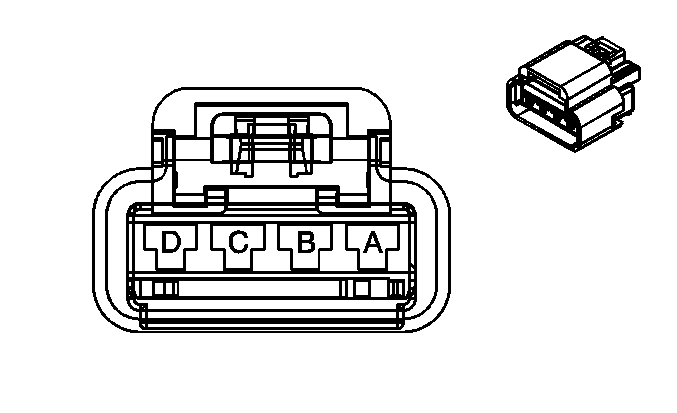
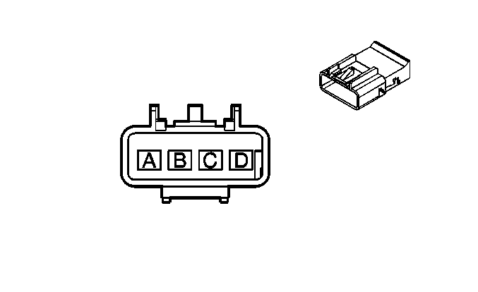
Pin | Wire Color | Circuit No. | Function | Pin | Wire Color | Circuit No. | Function | ||||||||
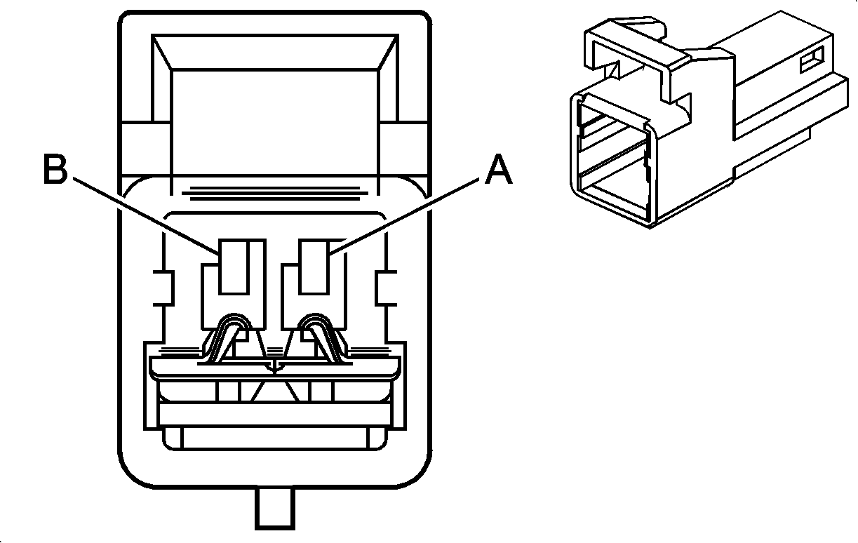
A | YE | 243 | Accessory Voltage | A | YE | 243 | Accessory Voltage | ||||||||
YE | 243 | Accessory Voltage | |||||||||||||
B | RD/WH | 1140 | Battery Positive Voltage | B | RD/WH | 1140 | Battery Positive Voltage | ||||||||
C | GY | 8 | Instrument Panel Lamp Supply Voltage | C | GY | 8 | Instrument Panel Lamp Supply Voltage | ||||||||
D | BK | 1150 | Ground | D | BK | 1150 | Ground | ||||||||
BK | 1150 | Ground | |||||||||||||

|
| ||||||||||||||
|---|---|---|---|---|---|---|---|---|---|---|---|---|---|---|---|
Connector Part Information |
| Connector Part Information |
| ||||||||||||
Pin | Wire Color | Circuit No. | Function | Pin | Wire Color | Circuit No. | Function | ||||||||
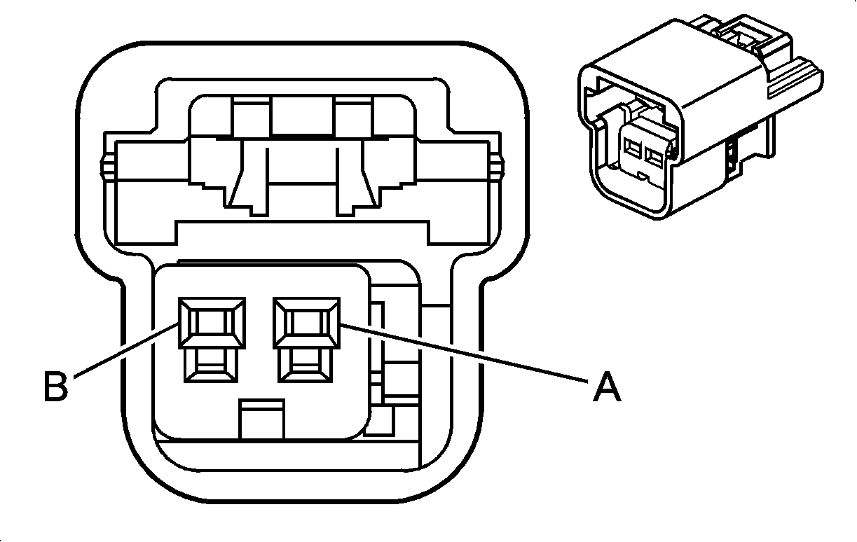
A | PK | 5020 | Roof Rail Module - Left - Low Control | A | PK | 5020 | Roof Rail Module - Left - Low Control | ||||||||
B | PU/WH | 5019 | Side Impact Module - LF High Control | B | PU/WH | 5019 | Side Impact Module - LF High Control | ||||||||

|

| ||||||||||||||
|---|---|---|---|---|---|---|---|---|---|---|---|---|---|---|---|
Connector Part Information |
| Connector Part Information |
| ||||||||||||
Pin | Wire Color | Circuit No. | Function | Pin | Wire Color | Circuit No. | Function | ||||||||
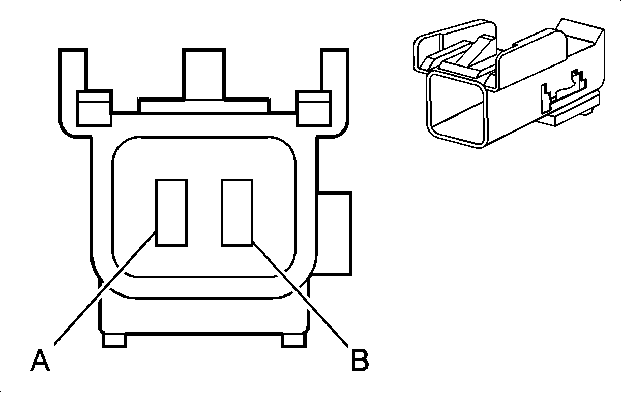
A | WH/BK | 5022 | Roof Rail Module - Right - Low Control | A | WH/BK | 5022 | Roof Rail Module - Right - Low Control | ||||||||
B | YE/BK | 5021 | Roof Rail Module - Right - High Control | B | YE/BK | 5021 | Roof Rail Module - Right - High Control | ||||||||
|
| ||||||||||||||
|---|---|---|---|---|---|---|---|---|---|---|---|---|---|---|---|
Connector Part Information |
| Connector Part Information |
| ||||||||||||
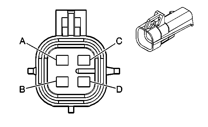
Pin | Wire Color | Circuit No. | Function | Pin | Wire Color | Circuit No. | Function | ||||||||
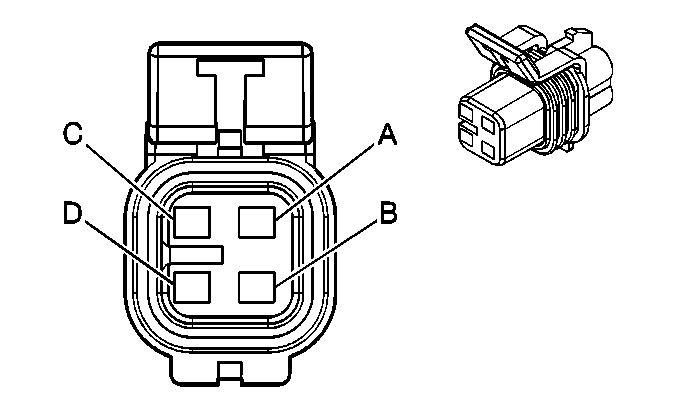
A | BARE | 1489 | Drain Wire | A | BARE | 1489 | Drain Wire | ||||||||
B | GY | 655 | Cellular Microphone Signal | B | GY | 655 | Cellular Microphone Signal | ||||||||
|
| ||||||||||||||
|---|---|---|---|---|---|---|---|---|---|---|---|---|---|---|---|
Connector Part Information |
| Connector Part Information |
| ||||||||||||
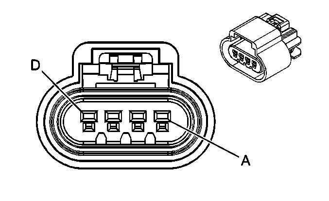
Pin | Wire Color | Circuit No. | Function | Pin | Wire Color | Circuit No. | Function | ||||||||
A | BK | 1550 | Ground | A | L-GN | 1550 | Ground | ||||||||
B | YE | 18 | Left Rear Stop/Turn Lamp Supply Voltage | B | PU | 18 | Left Rear Stop/Turn Lamp Supply Voltage | ||||||||
C | BN | 9 | Park Lamp Supply Voltage | C | RD | 9 | Park Lamp Supply Voltage | ||||||||
D | L-GN | 24 | Backup Lamp Supply Voltage | D | BN | 24 | Backup Lamp Supply Voltage | ||||||||

|

| ||||||||||||||
|---|---|---|---|---|---|---|---|---|---|---|---|---|---|---|---|
Connector Part Information |
| Connector Part Information |
| ||||||||||||
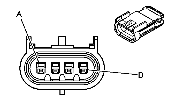
Pin | Wire Color | Circuit No. | Function | Pin | Wire Color | Circuit No. | Function | ||||||||
A | BK | 1450 | Ground | A | L-GN | 1450 | Ground | ||||||||
B | D-GN | 19 | Right Rear Stop/Turn Lamp Supply Voltage | B | PU | 19 | Right Rear Stop/Turn Lamp Supply Voltage | ||||||||
C | BN | 9 | Park Lamp Supply Voltage | C | RD | 9 | Park Lamp Supply Voltage | ||||||||
D | L-GN | 24 | Backup Lamp Supply Voltage | D | BN | 24 | Backup Lamp Supply Voltage | ||||||||
|
| ||||||||||||||
|---|---|---|---|---|---|---|---|---|---|---|---|---|---|---|---|
Connector Part Information |
| Connector Part Information |
| ||||||||||||
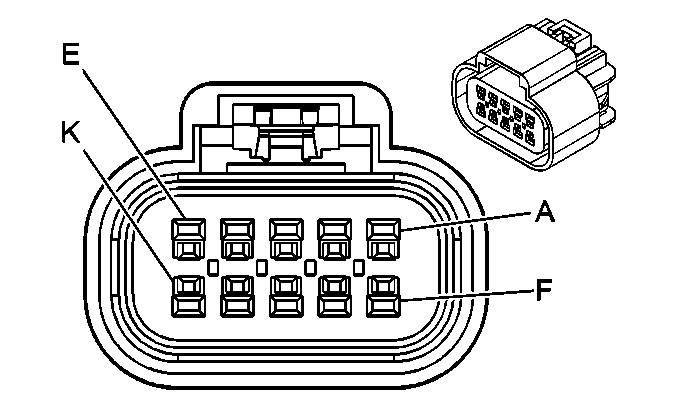
Pin | Wire Color | Circuit No. | Function | Pin | Wire Color | Circuit No. | Function | ||||||||
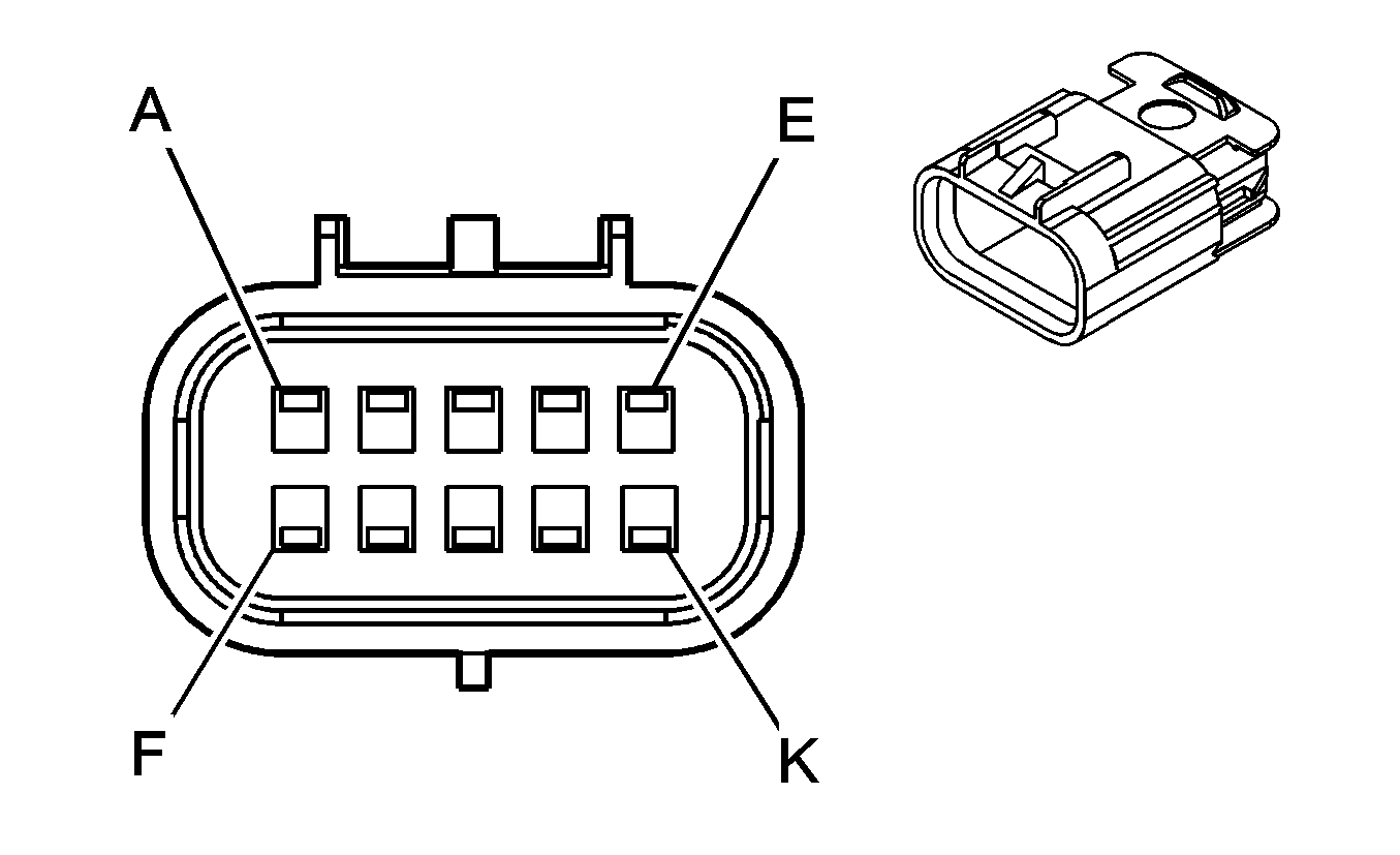
A | TN | 884 | Left Rear Wheel Speed Sensor Supply Voltage | A | TN | 884 | Left Rear Wheel Speed Sensor Supply Voltage | ||||||||
B | OG | 885 | Left Rear Wheel Speed Sensor Signal | B | OG | 885 | Left Rear Wheel Speed Sensor Signal | ||||||||
C | BN | 882 | Right Rear Wheel Speed Sensor Supply Voltage | C | BN | 882 | Right Rear Wheel Speed Sensor Supply Voltage | ||||||||
D | WH | 883 | Right Rear Wheel Speed Sensor Signal | D | WH | 883 | Right Rear Wheel Speed Sensor Signal | ||||||||
|
| ||||||||||||||
|---|---|---|---|---|---|---|---|---|---|---|---|---|---|---|---|
Connector Part Information |
| Connector Part Information |
| ||||||||||||
Pin | Wire Color | Circuit No. | Function | Pin | Wire Color | Circuit No. | Function | ||||||||
A | RD/WH | 1540 | Battery Positive Voltage | A | RD/WH | 1540 | Battery Positive Voltage | ||||||||
B | WH | 1310 | EVAP Canister Vent Solenoid Control | B | WH | 1310 | EVAP Canister Vent Solenoid Control | ||||||||
C | GY | 120 | Fuel Pump Supply Voltage | C | GY | 120 | Fuel Pump Supply Voltage | ||||||||
D | BK | 1250 | Ground | D | BK | 1250 | Ground | ||||||||
E | OG/BK | 469 | Low Reference | E | TN | 2759 | Low Reference | ||||||||
F | BK/WH | 651 | Low Reference | F | OG/BK | 1057 | Low Reference | ||||||||
G | PU | 1589 | Fuel Level Sensor Signal | G | PU | 1589 | Fuel Level Sensor Signal | ||||||||
H | D-GN | 890 | Fuel Tank Pressure Sensor Signal | H | D-GN | 890 | Fuel Tank Pressure Sensor Signal | ||||||||
J | GY | 705 | 5-Volt Reference | J | GY | 705 | 5-Volt Reference | ||||||||
K | -- | -- | Not Used | K | -- | -- | Not Available | ||||||||

|

| ||||||||||||||
|---|---|---|---|---|---|---|---|---|---|---|---|---|---|---|---|
Connector Part Information |
| Connector Part Information |
| ||||||||||||
Pin | Wire Color | Circuit No. | Function | Pin | Wire Color | Circuit No. | Function | ||||||||
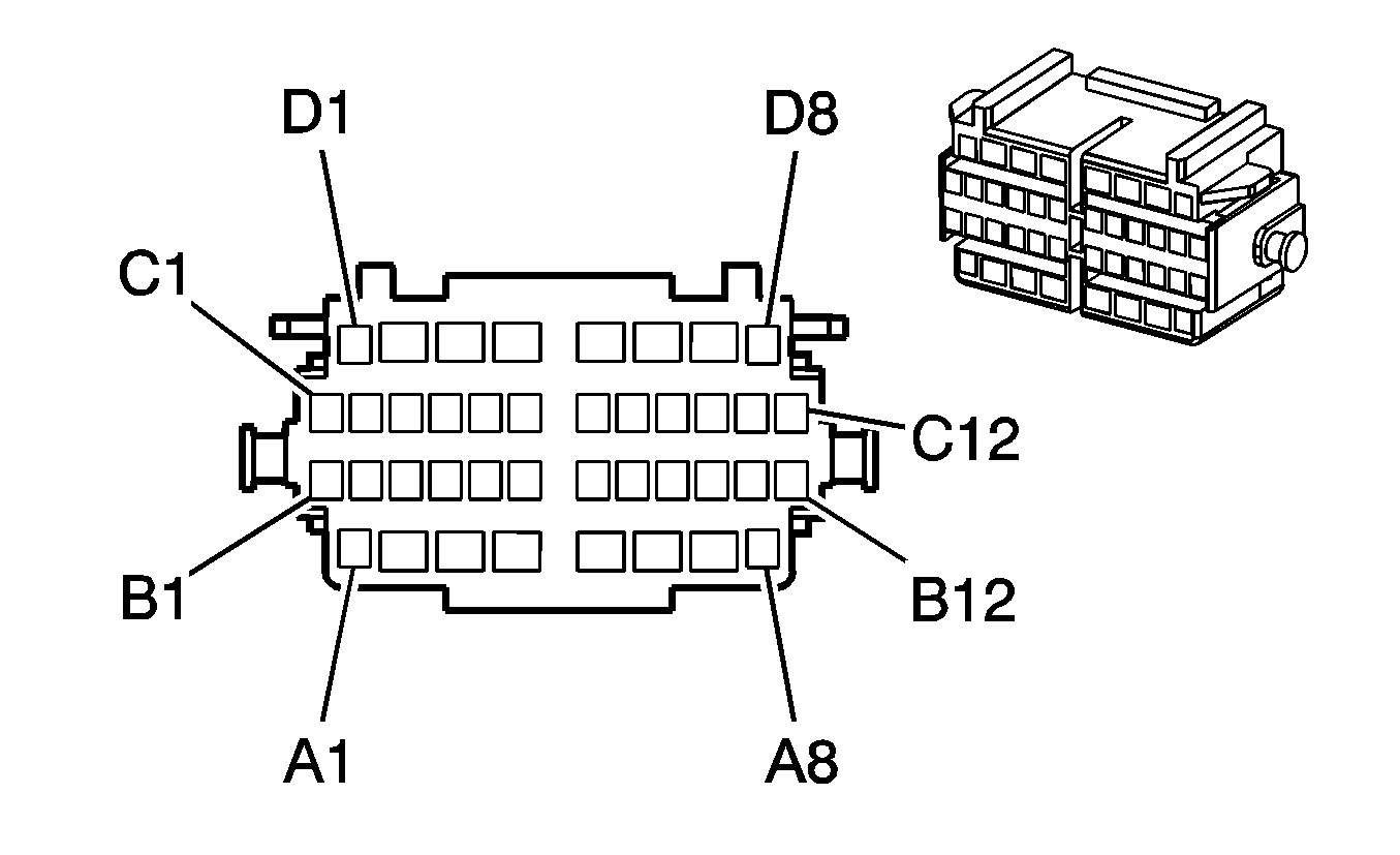
A | RD/WH | 1940 | Battery Positive Voltage | A | RD/WH | 1940 | Battery Positive Voltage | ||||||||
B | -- | -- | Not Used | B | -- | -- | Not Used | ||||||||
C | L-BU | 5027 | Sunroof Switch Data 1 Signal | C | L-BU | 5027 | Sunroof Switch Data 1 Signal | ||||||||
D | BN | 5028 | Sunroof Switch Data 2 Signal | D | GY | 5028 | Sunroof Switch Data 2 Signal | ||||||||
E | OG | 5029 | Sunroof Switch Data 3 Signal | E | PU | 5029 | Sunroof Switch Data 3 Signal | ||||||||
F | BK | 1350 | Ground | F | BK | 1350 | Ground | ||||||||
BK | 1350 | Ground | |||||||||||||
G | BK | 1350 | Ground | G | BK | 1350 | Ground | ||||||||
H | YE | 243 | Accessory Voltage | H | BN | 243 | Accessory Voltage | ||||||||
J | L-BU | 5304 | Front Sunshade Switch Open Signal | J | L-BU | 5304 | Front Sunshade Switch Open Signal | ||||||||
K | YE | 5305 | Front Sunshade Switch Close Signal | K | OG | 5305 | Front Sunshade Switch Close Signal | ||||||||
L | BN | 818 | Vehicle Speed Signal | L | D-BU | 818 | Vehicle Speed Signal | ||||||||
M | -- | -- | Not Used | M | WH | 5043 | Keyword 2000 Serial Data | ||||||||
|
| ||||||||||||||
|---|---|---|---|---|---|---|---|---|---|---|---|---|---|---|---|
Connector Part Information |
| Connector Part Information |
| ||||||||||||
Pin | Wire Color | Circuit No. | Function | Pin | Wire Color | Circuit No. | Function | ||||||||
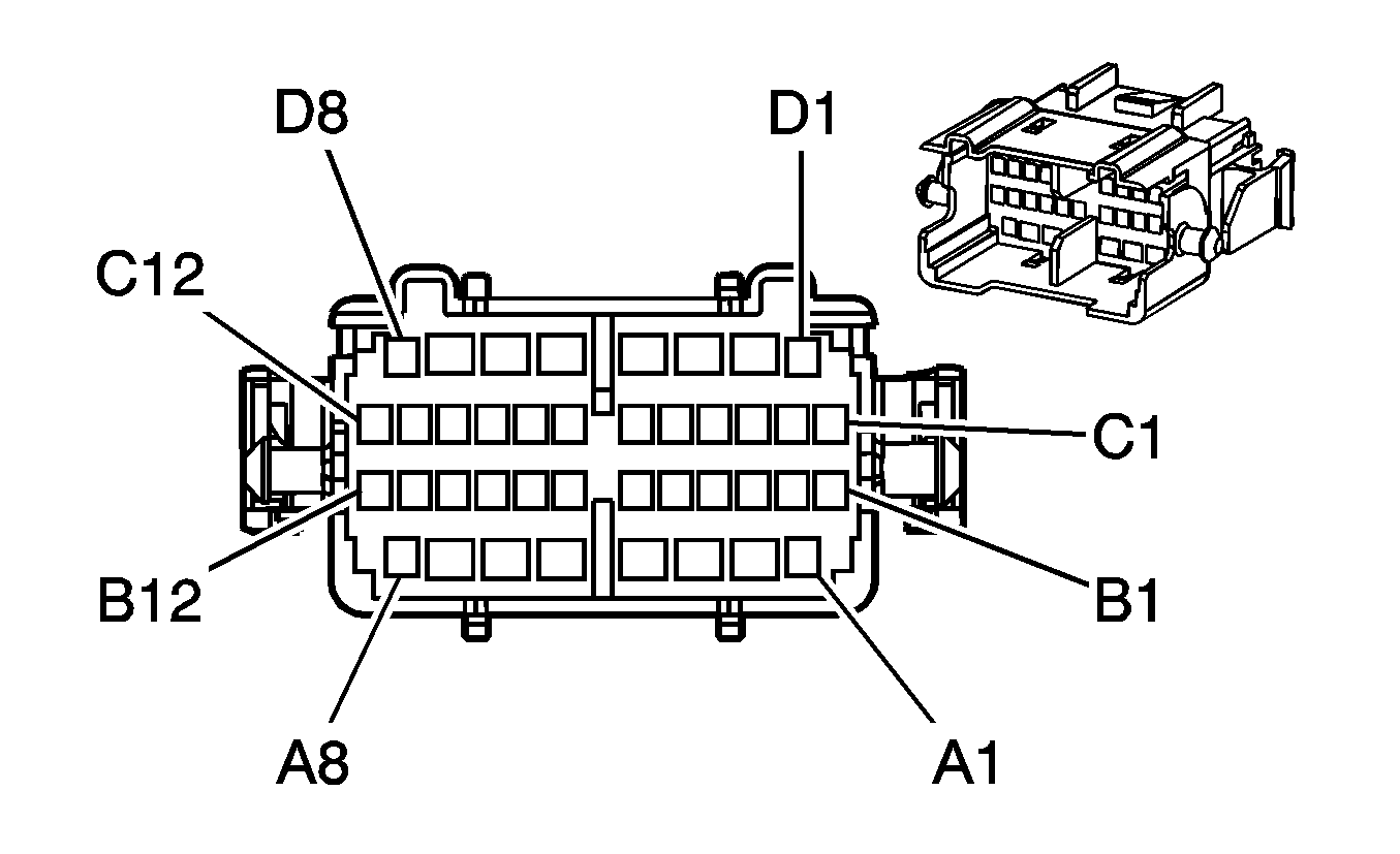
A1 | TN | 1856 | Left Front Tweeter Speaker Output (+) (U85) | A1 | TN | 1856 | Left Front Tweeter Speaker Output (+) (U85) | ||||||||
A2 | YE | 343 | Accessory Voltage | A2 | YE | 343 | Accessory Voltage | ||||||||
A3 | D-BU | 1307 | Power Window Master Switch Lockout Control | A3 | D-BU | 1307 | Power Window Master Switch Lockout Control | ||||||||
A4 | GY | 118 | Left Front Speaker Output (-) | A4 | GY | 118 | Left Front Speaker Output (-) | ||||||||
GY | 118 | Left Front Speaker Output (-) (UZ6) | |||||||||||||
A5 | TN | 201 | Left Front Speaker Output (+) | A5 | TN | 201 | Left Front Speaker Output (+) | ||||||||
TN | 201 | Left Front Speaker Output (+) (UZ6) | |||||||||||||
A6 | BK | 1250 | Ground | A6 | BK | 1250 | Ground | ||||||||
BK | 1250 | Ground | |||||||||||||
A7 | BK | 1150 | Ground | A7 | BK | 1150 | Ground | ||||||||
A8 | -- | -- | Not Used | A8 | -- | -- | Not Used | ||||||||
B1-B2 | -- | -- | Not Used | B1-B2 | -- | -- | Not Used | ||||||||
B3 | WH | 682 | Door Lock Lock/Unlock Signal | B3 | WH | 682 | Door Lock Lock/Unlock Signal | ||||||||
B4 | GY | 8 | Instrument Panel Lamp Supply Voltage | B4 | GY | 8 | Instrument Panel Lamp Supply Voltage | ||||||||
B5 | TN | 694 | Driver Door Lock Actuator Unlock Control | B5 | TN | 694 | Driver Door Lock Actuator Unlock Control | ||||||||
B6 | GY/BK | 295 | Door Lock Actuator Lock Control | B6 | GY | 295 | Door Lock Actuator Lock Control | ||||||||
B7 | GY/BK | 745 | Left Front Door Ajar Switch Signal | B7 | GY/BK | 745 | Left Front Door Ajar Switch Signal | ||||||||
B8 | GY | 8 | Instrument Panel Lamp Supply Voltage | B8 | GY | 8 | Instrument Panel Lamp Supply Voltage | ||||||||
B9 | L-GN | 262 | Driver Door Key Switch Unlock Signal | B9 | L-GN | 262 | Driver Door Key Switch Unlock Signal | ||||||||
B10 | YE | 2131 | Side Impact Sensing Module - Left - Voltage (AY0) | B10 | YE | 2131 | Side Impact Sensing Module - Left - Voltage (AY0) | ||||||||
B11 | WH | 2132 | Side Impact Sensing Module - Left - Signal (AY0) | B11 | WH | 2132 | Side Impact Sensing Module - Left - Signal (AY0) | ||||||||
B12 | -- | -- | Not Used | B12 | -- | -- | Not Used | ||||||||
C1-C2 | -- | -- | Not Used | C1-C2 | -- | -- | Not Used | ||||||||
C3 | RD/WH | 640 | Battery Positive Voltage | C3 | RD/WH | 640 | Battery Positive Voltage | ||||||||
C4 | BK | 1150 | Ground | C4 | BK | 1150 | Ground | ||||||||
C5 | GY | 8 | Instrument Panel Lamp Supply Voltage | C5 | GY | 8 | Instrument Panel Lamp Supply Voltage | ||||||||
C6 | OG/WH | 881 | Right Mirror Motor Right Control | C6 | OG/WH | 881 | Right Mirror Motor Right Control | ||||||||
C7 | PU/WH | 889 | Right Mirror Motor Down Control | C7 | PU/WH | 889 | Right Mirror Motor Down Control | ||||||||
C8 | GY | 90 | Passenger Mirror Motor Left/Up Control | C8 | GY | 90 | Passenger Mirror Motor Left/Up Control | ||||||||
C9 | BK | 1150 | Ground | C9 | BK | 1150 | Ground | ||||||||
C10 | BN/WH | 2091 | Trunk Release Switch Supply Voltage | C10 | BN/WH | 2091 | Trunk Release Switch Supply Voltage | ||||||||
C11-C12 | -- | -- | Not Used | C11-C12 | -- | -- | Not Used | ||||||||
D1 | YE | 1956 | Left Front Tweeter Speaker Output (-) (U85) | D1 | YE | 1956 | Left Front Tweeter Speaker Output (-) (U85) | ||||||||
D2 | L-BU | 166 | Power Window Master Switch Right Front Up Signal | D2 | L-BU | 166 | Power Window Master Switch Right Front Up Signal | ||||||||
D3 | TN | 167 | Power Window Master Switch Right Front Down Signal | D3 | TN | 167 | Power Window Master Switch Right Front Down Signal | ||||||||
D4 | D-GN | 168 | Power Window Master Switch Left Rear Up Signal | D4 | D-GN | 168 | Power Window Master Switch Left Rear Up Signal | ||||||||
D5 | PU | 169 | Power Window Master Switch Left Rear Down Signal | D5 | PU | 169 | Power Window Master Switch Left Rear Down Signal | ||||||||
D6 | L-GN | 170 | Power Window Master Switch Right Rear Up Signal | D6 | L-GN | 170 | Power Window Master Switch Right Rear Up Signal | ||||||||
D7 | PU | 171 | Power Window Master Switch Right Rear Down Signal | D7 | PU | 171 | Power Window Master Switch Right Rear Down Signal | ||||||||
D8 | -- | -- | Not Used | D8 | -- | -- | Not Used | ||||||||
|
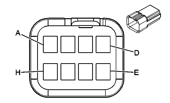
| ||||||||||||||
|---|---|---|---|---|---|---|---|---|---|---|---|---|---|---|---|
Connector Part Information |
| Connector Part Information |
| ||||||||||||
Pin | Wire Color | Circuit No. | Function | Pin | Wire Color | Circuit No. | Function | ||||||||
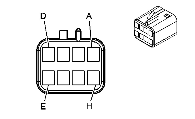
A | GY | 8 | Instrument Panel Lamp Supply Voltage | A | GY | 8 | Instrument Panel Lamp Supply Voltage | ||||||||
B | WH | 682 | Door Lock Lock/Unlock Signal | B | WH | 682 | Door Lock Lock/Unlock Signal | ||||||||
C | BK | 1250 | Ground | C | BK | 1250 | Ground | ||||||||
D | TN | 1856 | Left Front Tweeter Speaker Output (+) (U85) | D | TN | 1856 | Left Front Tweeter Speaker Output (+) (U85) | ||||||||
TN | 201 | Left Front Speaker Output (+) (UZ6) | |||||||||||||
E | YE | 1956 | Left Front Tweeter Speaker Output (-) (U85) | E | YE | 1956 | Left Front Tweeter Speaker Output (-) (U85) | ||||||||
GY | 118 | Left Front Speaker Output (-) (UZ6) | |||||||||||||
F | GY | 8 | Instrument Panel Lamp Supply Voltage | F | GY | 8 | Instrument Panel Lamp Supply Voltage | ||||||||
G | BK | 1150 | Ground | G | BK | 1150 | Ground | ||||||||
H | BN/WH | 2091 | Trunk Release Switch Supply Voltage | H | BN/WH | 2091 | Trunk Release Switch Supply Voltage | ||||||||

|

| ||||||||||||||
|---|---|---|---|---|---|---|---|---|---|---|---|---|---|---|---|
Connector Part Information |
| Connector Part Information |
| ||||||||||||
Pin | Wire Color | Circuit No. | Function | Pin | Wire Color | Circuit No. | Function | ||||||||
A1 | L-GN | 1852 | Right Front Tweeter Speaker Output (+) (U85) | A1 | L-GN | 1852 | Right Front Tweeter Speaker Output (+) (U85) | ||||||||
A2 | YE | 343 | Accessory Voltage | A2 | YE | 343 | Accessory Voltage | ||||||||
A3 | -- | -- | Not Used | A3 | -- | -- | Not Used | ||||||||
A4 | D-GN | 117 | Right Front Speaker Output (-) | A4 | D-GN | 117 | Right Front Speaker Output (-) | ||||||||
D-GN | 117 | Right Front Speaker Output (-) (UZ6) | |||||||||||||
A5 | L-GN | 200 | Right Front Speaker Output (+) | A5 | L-GN | 200 | Right Front Speaker Output (+) | ||||||||
L-GN | 200 | Right Front Speaker Output (+) (UZ6) | |||||||||||||
A6 | BK | 1250 | Ground | A6 | BK | 1250 | Ground | ||||||||
BK | 1250 | Ground | |||||||||||||
A7-A8 | -- | -- | Not Used | A7-A8 | -- | -- | Not Used | ||||||||
B1 | -- | -- | Not Used | B1 | -- | -- | Not Used | ||||||||
B2 | BK | 1150 | Ground | B2 | BK | 1150 | Ground | ||||||||
B3 | WH | 682 | Door Lock Lock/Unlock Signal | B3 | WH | 682 | Door Lock Lock/Unlock Signal | ||||||||
B4 | GY | 8 | Instrument Panel Lamp Supply Voltage | B4 | GY | 8 | Instrument Panel Lamp Supply Voltage | ||||||||
B5 | TN | 294 | Door Lock Actuator Unlock Control | B5 | TN | 294 | Door Lock Actuator Unlock Control | ||||||||
B6 | GY/BK | 295 | Door Lock Actuator Lock Control | B6 | GY | 295 | Door Lock Actuator Lock Control | ||||||||
B7 | TN/WH | 746 | Right Front Door Ajar Switch Signal | B7 | TN/WH | 746 | Right Front Door Ajar Switch Signal | ||||||||
B8-B9 | -- | -- | Not Used | B8-B9 | -- | -- | Not Used | ||||||||
B10 | TN | 2133 | Side Impact Sensing Module - Right - Voltage (AY0) | B10 | TN | 2133 | Side Impact Sensing Module - Right - Voltage (AY0) | ||||||||
B11 | D-GN | 2134 | Side Impact Sensing Module - Right - Signal (AY0) | B11 | D-GN | 2134 | Side Impact Sensing Module - Right - Signal (AY0) | ||||||||
B12 | -- | -- | Not Used | B12 | -- | -- | Not Used | ||||||||
C1 | -- | -- | Not Used | C1 | -- | -- | Not Used | ||||||||
C2 | GY | 90 | Passenger Mirror Motor Left/Up Control | C2 | GY | 90 | Passenger Mirror Motor Left/Up Control | ||||||||
C3-C5 | -- | -- | Not Used | C3-C5 | -- | -- | Not Used | ||||||||
C6 | OG/WH | 881 | Passenger Mirror Motor Right Control | C6 | OG/WH | 881 | Passenger Mirror Motor Right Control | ||||||||
C7 | -- | -- | Not Used | C7 | -- | -- | Not Used | ||||||||
C8 | PU/WH | 889 | Right Mirror Motor Down Control | C8 | PU/WH | 889 | Right Mirror Motor Down Control | ||||||||
C9-C12 | -- | -- | Not Used | C9-C12 | -- | -- | Not Used | ||||||||
D1 | PU | 1952 | Right Front Tweeter Speaker Output (-) (U85) | C8 | PU | 1952 | Right Front Tweeter Speaker Output (-) (U85) | ||||||||
D2-D3 | -- | -- | Not Used | D1-D3 | -- | -- | Not Used | ||||||||
D4 | L-BU | 166 | Power Window Master Switch Right Front Up Signal | D4 | L-BU | 166 | Power Window Master Switch Right Front Up Signal | ||||||||
D5 | TN | 167 | Power Window Master Switch Right Front Down Signal | D5 | TN | 167 | Power Window Master Switch Right Front Down Signal | ||||||||
D6-D8 | -- | -- | Not Used | D6-D8 | -- | -- | Not Used | ||||||||

|

| ||||||||||||||
|---|---|---|---|---|---|---|---|---|---|---|---|---|---|---|---|
Connector Part Information |
| Connector Part Information |
| ||||||||||||
Pin | Wire Color | Circuit No. | Function | Pin | Wire Color | Circuit No. | Function | ||||||||
A | GY | 8 | Instrument Panel Lamp Supply Voltage | A | GY | 8 | Instrument Panel Lamp Supply Voltage | ||||||||
B | WH | 682 | Door Lock Lock/Unlock Signal | B | WH | 682 | Door Lock Lock/Unlock Signal | ||||||||
C | BK | 1250 | Ground | C | BK | 1250 | Ground | ||||||||
D | L-GN | 1852 | Right Front Tweeter Speaker Output (+) (U85) | D | L-GN | 1852 | Right Front Tweeter Speaker Output (+) (U85) | ||||||||
L-GN | 200 | Right Front Speaker Output (+) (UZ6) | |||||||||||||
E | PU | 1952 | Right Front Tweeter Speaker Output (-) (U85) | E | PU | 1952 | Right Front Tweeter Speaker Output (-) (U85) | ||||||||
D-GN | 117 | Right Front Speaker Output (-) (UZ6) | |||||||||||||
F-H | -- | -- | Not Used | F-H | -- | -- | Not Used | ||||||||
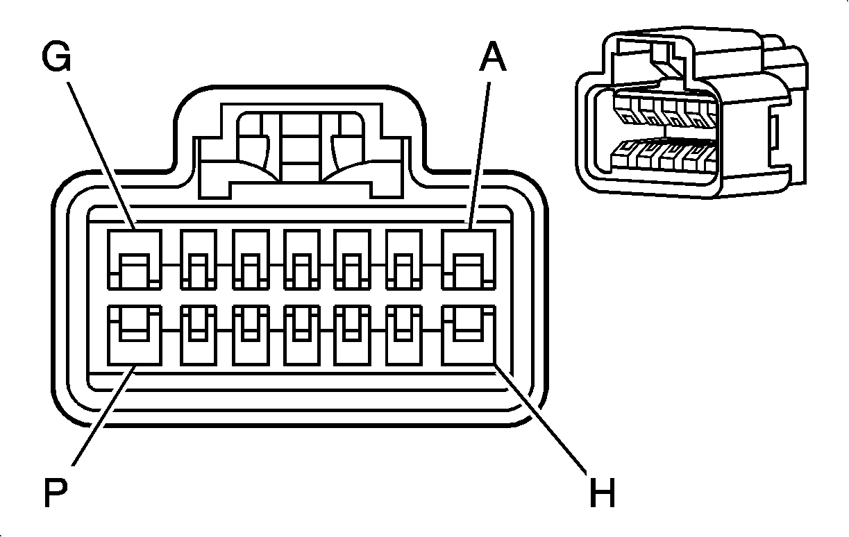
|
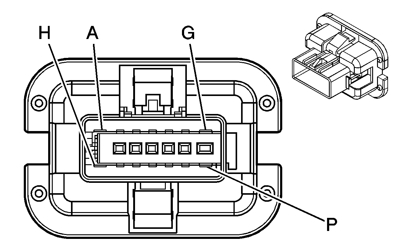
| ||||||||||||||
|---|---|---|---|---|---|---|---|---|---|---|---|---|---|---|---|
Connector Part Information |
| Connector Part Information |
| ||||||||||||
Pin | Wire Color | Circuit No. | Function | Pin | Wire Color | Circuit No. | Function | ||||||||
A | D-GN | 168 | Power Window Master Switch Left Rear Up Signal | A | D-GN | 168 | Power Window Master Switch Left Rear Up Signal | ||||||||
B | L-BU/BK | 747 | Left Rear Door Ajar Switch Signal | B | L-BU/BK | 747 | Left Rear Door Ajar Switch Signal | ||||||||
C | GY | 295 | Door Lock Actuator Lock Control | C | GY | 295 | Door Lock Actuator Lock Control | ||||||||
D | TN | 294 | Door Lock Actuator Unlock Control | D | TN | 294 | Door Lock Actuator Unlock Control | ||||||||
E-F | -- | -- | Not Used | E-F | -- | -- | Not Used | ||||||||
G | PU | 169 | Power Window Master Switch Left Rear Down Signal | G | PU | 169 | Power Window Master Switch Left Rear Down Signal | ||||||||
H | D-BU | 1307 | Power Window Master Switch Lockout Control | H | D-BU | 1307 | Power Window Master Switch Lockout Control | ||||||||
J | BK | 1250 | Ground | J | BK | 1250 | Ground | ||||||||
K-P | -- | -- | Not Used | K-P | -- | -- | Not Used | ||||||||

|

| ||||||||||||||
|---|---|---|---|---|---|---|---|---|---|---|---|---|---|---|---|
Connector Part Information |
| Connector Part Information |
| ||||||||||||
Pin | Wire Color | Circuit No. | Function | Pin | Wire Color | Circuit No. | Function | ||||||||
A | L-GN | 170 | Power Window Master Switch Right Rear Up Signal | A | L-GN | 170 | Power Window Master Switch Right Rear Up Signal | ||||||||
B | L-GN/BK | 748 | Right Rear Door Ajar Switch Signal | B | L-GN/BK | 748 | Right Rear Door Ajar Switch Signal | ||||||||
C | GY | 295 | Door Lock Actuator Lock Control | C | GY | 295 | Door Lock Actuator Lock Control | ||||||||
D | TN | 294 | Door Lock Actuator Unlock Control | D | TN | 294 | Door Lock Actuator Unlock Control | ||||||||
E-F | -- | -- | Not Used | E-F | -- | -- | Not Used | ||||||||
G | PU | 171 | Power Window Master Switch Right Rear Down Signal | G | PU | 171 | Power Window Master Switch Right Rear Down Signal | ||||||||
H | D-BU | 1307 | Power Window Master Switch Lockout Control | H | D-BU | 1307 | Power Window Master Switch Lockout Control | ||||||||
J | BK | 1250 | Ground | J | BK | 1250 | Ground | ||||||||
K-P | -- | -- | Not Used | K-P | -- | -- | Not Used | ||||||||
