GM Service Manual Online
For 1990-2009 cars only

All of the sensors and the input switches can be diagnosed with the use of a scan tool. The following is a short description of the sensors and switches. The scan tool can also be used in order to compare the values for a normal running engine with the engine being diagnosed.

Camshaft Position Sensor (CMP)


Object Number: 1697734  Size: SH

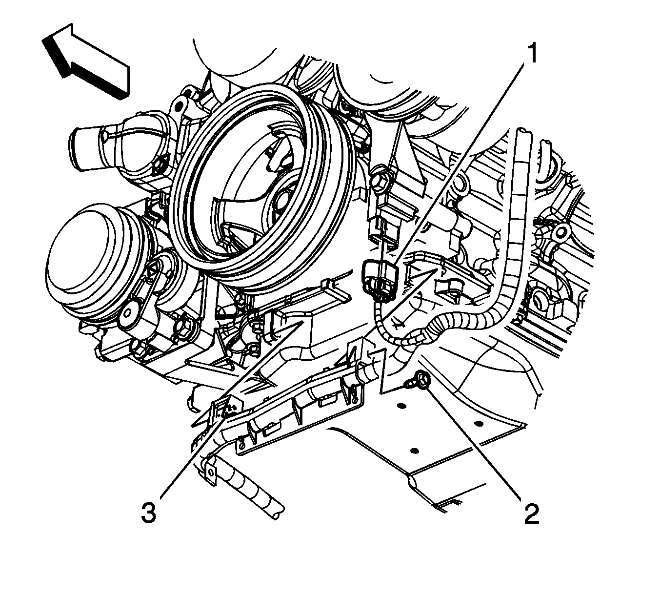
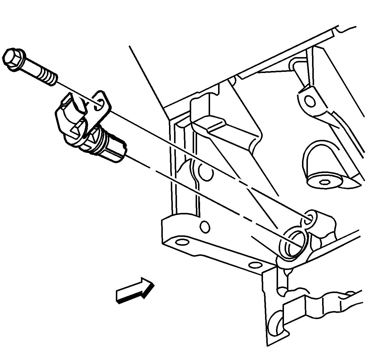
The camshaft position (CMP) sensor is a 3-wire sensor that provides a digital output signal. The CMP harness connector 1 consists of the engine control module (ECM) supplied 5-volt reference circuit, a low reference circuit between the CMP sensor and the ECM, and an output signal circuit from the CMP sensor to the ECM. The CMP sensor detects magnetic flux changes between the teeth and slots on the 4-tooth reluctor wheel. The CMP sensor provides a digital ON/OFF DC voltage of varying frequency, with 4 varying width output pulses, per each camshaft revolution. The frequency of the CMP sensor output signal depends on the speed of the camshaft. The ECM will recognize the narrow and wide tooth patterns to identify camshaft position, or which cylinder is in compression and which is in exhaust. The information is then used to determine the correct time and sequence for fuel injection and ignition spark events. The ECM also uses the CMP sensor output signal to determine the camshaft relative position to the crankshaft position.

Crankshaft Position Sensor (CKP)


Object Number: 55322  Size: SH

The crankshaft position (CKP) sensor is a 3-wire sensor that provides a digital output signal. The circuits consist of an engine control module (ECM) supplied 5-volt reference circuit, a low reference circuit between the CKP sensor and the ECM, and an output signal circuit from the CKP sensor to the ECM. The CKP sensor detects magnetic flux changes of the teeth and slots of the 58-tooth reluctor on the crankshaft. The CKP sensor provides an ON/OFF DC voltage of varying frequency, with 58 output pulses per each crankshaft revolution. The frequency of the CKP sensor output signal depends on the speed of the crankshaft. The CKP sensor sends a digital square wave signal, which represents an image of the teeth on the reluctor wheel, to the ECM. The 12 degree reference gap on the reluctor wheel is used to identify crankshaft position. The CKP information, along with the camshaft position (CMP) sensor information is used to determine the correct time and sequence for fuel injection, ignition spark events, detect cylinder misfire, and the camshaft to crankshaft relative position.

Engine Coolant Temperature (ECT) Sensor


Object Number: 13578  Size: SH
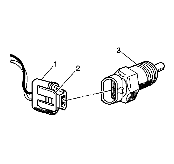
(1)ECT Electrical Connector
(2)Connector Tab
(3)Engine Coolant Temperature (ECT) Sensor

The engine coolant temperature sensor is a thermistor (a resistor which changes value based on temperature) mounted in the left cylinder head. Low coolant temperature produces a high resistance, 100,000 ohms at -38°C (-39°F), while high temperature causes low resistance, 70 ohms at 130°C (266°F).

The ECM supplies a 5.0 volt signal to the ECT sensor. The ECM measures the voltage drop across the sensor. The voltage will be high when the engine is cold. The voltage will be low when the engine is hot. The ECM calculates the engine coolant temperature by measuring the voltage. The engine coolant temperature is a critical input for the ECM controls.

The scan tool displays engine coolant temperature in degrees. When the engine starts the engine coolant temperature should rise steadily to approximately 90°C (194°F) then stabilize when the thermostat opens. The engine coolant temperature and intake air temperature parameter displays should be close to each other if the engine has not been run for several hours (overnight).
Heated Oxygen Sensors (HO2S)


Object Number: 13576  Size: LH
(1)Four Wire In-Line Connector
(2)Heater Termination
(3)Water Shield Assembly
(4)Sensor Lead
(5)Flat Seat Shell
(6)Seat Gasket
(7)Outer Electrode and Protective Coating
(8)Rod Heater
(9)Inner Electrode
(10)Zirconia Element
(11)Insulator
(12)Clip Ring
(13)Gripper

The Heated Oxygen Sensors are mounted in the exhaust system where they can monitor the oxygen content of the exhaust gas stream. The oxygen present in the exhaust gas reacts with the sensor to produce a voltage output. This voltage should constantly fluctuate from approximately 100 mV (high oxygen content=lean mixture) to 900 mV (low oxygen content=rich mixture). The heated oxygen sensor voltage can be monitored with a scan tool. By monitoring the voltage output of the oxygen sensor, the ECM calculates the pulse width command to operate the fuel injectors (lean mixture/low HO2S voltage=rich command, rich mixture/high HO2S voltage=lean command).

Idle Air Control (IAC) Valve


Object Number: 12767  Size: SH

The purpose of the Idle Air Control (IAC) valve is to control engine idle speed, while preventing stalls due to changes in engine load. The IAC valve, mounted in the throttle body, controls bypass air around the throttle plate. By moving a conical valve, known as a pintle, in (to decrease air flow) or out (to increase air flow), a controlled amount of air can move around the throttle plate. The IAC pintle moves in small steps called counts. If the engine RPM is too low, the ECM will command the IAC pintle open, resulting in more air being bypassed around the throttle plate to increase RPM. If the RPM is too high, the ECM will command the IAC pintle closed, allowing less air to be bypassed around the throttle plate, decreasing RPM.

During idle, the proper position of the IAC pintle is calculated by the ECM based on battery voltage, coolant temperature, engine load, and engine RPM. If the RPM drops below a specified value, and the throttle plate is closed, the ECM senses a near stall condition. The ECM will then calculate a new IAC pintle position to prevent stalls.

The position of the IAC pintle affects engine start up and the idle characteristics of the vehicle. If the IAC pintle is open full, too much air will be allowed into the manifold. This results in high idle speed, along with possible hard starting and a lean air/fuel ratio. If the IAC pintle is stuck closed, too little air will be allowed in the manifold. This results in a low idle speed, along with possible hard starting and a rich air/fuel ratio. If the IAC pintle is stuck part way open, the idle may be high or low and will not respond to changes in engine load.

Intake Air Temperature (IAT) Sensor


Object Number: 2037922  Size: SH

The Intake Air Temperature (IAT) sensor is a thermistor which changes value based on the temperature of air entering the engine. Low temperature produces a high resistance, 100,000 ohms at -38°C (-39°F). A high temperature causes low resistance, 70 ohms at 130°C (266°F). The ECM supplies a 5 volt signal to the sensor. The ECM measures the voltage drop across the sensor. The voltage will be high when the incoming air is cold, and low when the air is hot. The ECM calculates the incoming air temperature by measuring the IAT voltage. The IAT sensor signal is used to adjust spark timing according to incoming air density.

The scan tool displays the temperature of the air entering the engine, which should be close to ambient air temperature when the engine is cold. The temperature should rise as under-hood temperature increases. The engine coolant temperature and intake air temperature parameter displays should be close to each other if the engine has not been run for several hours (overnight).
Knock Sensors (KS)

A Knock Sensor (KS) system is used in order to control spark knock. The KS system is designed to retard spark timing up to 20 degrees in order to reduce spark knock in the engine. This allows the engine to use maximum spark advance to improve driveability and fuel economy.

The knock sensor system is used to detect engine detonation. The knock sensors produce an AC voltage which is sent to the ECM. The ECM retards the spark timing based on signals from the KS sensors. The amount of AC voltage produced by the sensors is determined by the amount of knock. The ECM then adjusts the Ignition Control (IC) to reduce the spark knock.

Manifold Absolute Pressure (MAP) Sensor


Object Number: 2037921  Size: SH

The Manifold Absolute Pressure (MAP) sensor (1) responds to changes in the intake manifold pressure. The pressure changes as a result of engine load and speed. The map sensor converts this to a voltage output.

A closed throttle on engine coast down produces a relatively low MAP output voltage. A wide open throttle produces a high MAP output voltage. This high output voltage is produced because the pressure inside the manifold is the same as outside the manifold. The MAP is inversely proportional to what is measured on a vacuum gauge. The MAP sensor is used for the following:

    • Altitude determination.
    • Ignition timing control.
    • Speed density fuel management default.

Throttle Position (TP) Sensor


Object Number: 12766  Size: SH

The Throttle Position (TP) sensor is a potentiometer connected to the throttle shaft on the throttle body. The ECM calculates throttle position by monitoring the voltage on the signal circuit. As the throttle valve angle is changed (accelerator pedal moved), the TP sensor signal voltage also changes. At a closed throttle position, the output of the TP sensor is low. As the throttle valve opens, the output increases. The ECM calculates fuel delivery based on throttle valve angle (driver demand). A broken or loose TP sensor may cause intermittent bursts of fuel from the fuel injectors. An unstable idle may also be noticed because the ECM detects throttle movement.

Vehicle Speed Sensor (VSS)


Object Number: 13640  Size: SH

The Vehicle Speed Sensor (VSS) is a pulse counter type input that informs the ECM how fast the vehicle is traveling. The VSS system uses an inductive sensor mounted in the tail housing of the transmission and a toothed reluctor wheel on the tail shaft. The teeth of the reluctor wheel alternately interfere with the magnetic field of the sensor creating an induced voltage pulse as the reluctor rotates.

The VSS produces an AC voltage signal that increases with vehicle speed. The ECM processes this signal and sends it to the Instrument Panel.