Using a Scan Tool
- Remove the air cleaner (if necessary). Refer to Air Cleaner Assembly Replacement .
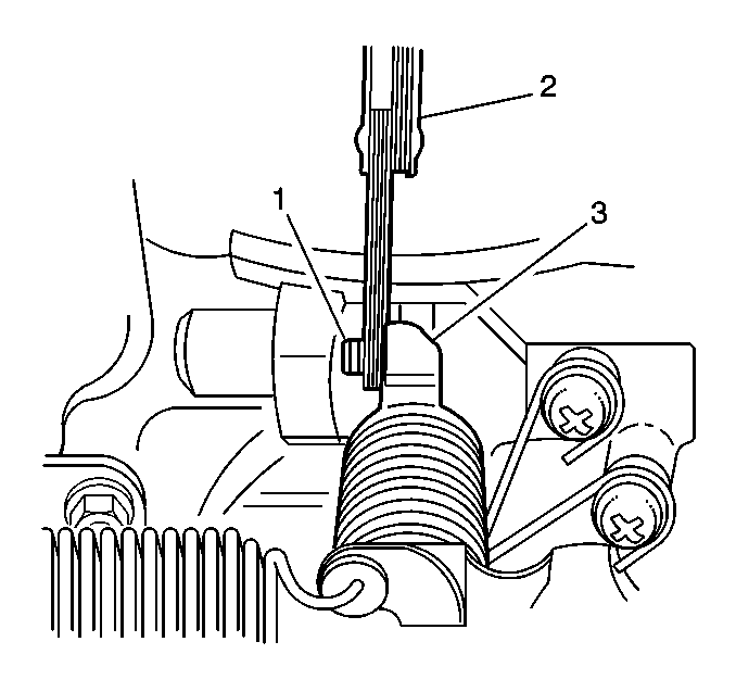
- Insert a 3.5 mm (0.14 inch) feeler gage (2) between the throttle stop screw (1) and the throttle lever (3).
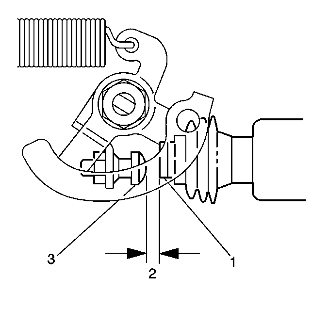
- Inspect the ISC motor plunger. If the ISC motor plunger (1) is contacting the throttle lever screw (3), then the engine must be brought to operating temperature. There must be no contact (2) between the ISC motor plunger and the throttle lever screw.
- Turn ON the ignition.
- Observe the TP sensor voltage on the scan tool. The TP sensor voltage reading should be 0.98 to 1.02 volts.
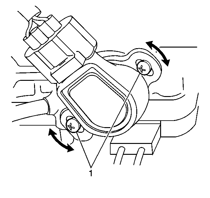
- If the TP sensor voltage IS NOT 0.98 to 1.02 volts, loosen the TP sensor screws (1) and turn the TP sensor until the voltage reading is 0.98 to 1.02 volts.
- Tighten the TP sensor screws (1).
- Replace the TP sensor if a TP sensor voltage reading of 0.98 to 1.02 volts cannot be obtained. Refer to Throttle Position Sensor Replacement .
- Install the air cleaner. Refer to Air Cleaner Assembly Replacement .


Notice: Use the correct fastener in the correct location. Replacement fasteners must be the correct part number for that application. Fasteners requiring replacement or fasteners requiring the use of thread locking compound or sealant are identified in the service procedure. Do not use paints, lubricants, or corrosion inhibitors on fasteners or fastener joint surfaces unless specified. These coatings affect fastener torque and joint clamping force and may damage the fastener. Use the correct tightening sequence and specifications when installing fasteners in order to avoid damage to parts and systems.
Tighten
Tighten the TP sensor screws to 2.0 N·m (18 lb in).
Using a Digital Multimeter (DMM)
- Remove the air cleaner (if necessary). Refer to Air Cleaner Assembly Replacement .
- Insert a 3.5 mm (0.14 in.) feeler gage (2) between the throttle stop screw (1) and the throttle lever (3).
- Inspect the idle speed control (ISC) motor plunger. If the ISC motor plunger (1) is contacting the throttle lever screw (3), then the engine must be brought to operating temperature. There must be no contact (2) between the ISC motor plunger and the throttle lever screw.
- Back probe the throttle position (TP) sensor signal circuit at the powertrain control module electrical connector to ground.
- Turn ON the ignition.
- Observe the TP sensor voltage on the DMM. The TP sensor voltage reading should be 0.98 to 1.02 volts.
- If the TP sensor voltage IS NOT 0.98 to 1.02 volts, loosen the TP sensor screws (1) and turn the TP sensor until the voltage reading is 0.98 to 1.02 volts.
- Tighten the TP sensor screws (1).
- If a TP sensor voltage reading of 0.98 to 1.02 volts cannot be obtained, replace the TP sensor. Refer to Throttle Position Sensor Replacement .
- Install the air cleaner. Refer to Air Cleaner Assembly Replacement .


Notice: Use the correct fastener in the correct location. Replacement fasteners must be the correct part number for that application. Fasteners requiring replacement or fasteners requiring the use of thread locking compound or sealant are identified in the service procedure. Do not use paints, lubricants, or corrosion inhibitors on fasteners or fastener joint surfaces unless specified. These coatings affect fastener torque and joint clamping force and may damage the fastener. Use the correct tightening sequence and specifications when installing fasteners in order to avoid damage to parts and systems.
Tighten
Tighten the TP sensor screws to 2.0 N·m (18 lb in).
