Removal Procedure
- Unscrew the gearshift control lever knob counterclockwise in order to remove the gearshift control lever knob from the gearshift control lever.
- Remove the gearshift control lever upper boot from the gearshift control lever.
- Remove the following components from the vehicle:
- Remove the 4 gearshift control lever housing nuts (2) from the gearshift control lever housing studs.
- Raise and suitably support the vehicle. Refer to Lifting and Jacking the Vehicle in General Information.
- Remove the gearshift control shaft rear-through bolt and nut (3) from the gearshift control shaft (1).
- Remove the following components from the gearshift control lever guide plate (4):
- Remove the gearshift control lever from the vehicle.
- Remove the gearshift control lever boot cover from the gearshift control lever.
- Remove the gearshift control lever lower boot from the gearshift control lever.
- Remove the following components from the gearshift control lever housing (2):
- Remove the following components from the gearshift control lever guide plate (2):
- Remove the gearshift control lever lower seat (3) from the gearshift control lever.
| • | Six screws |
| • | The console |
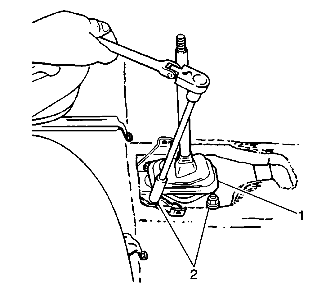
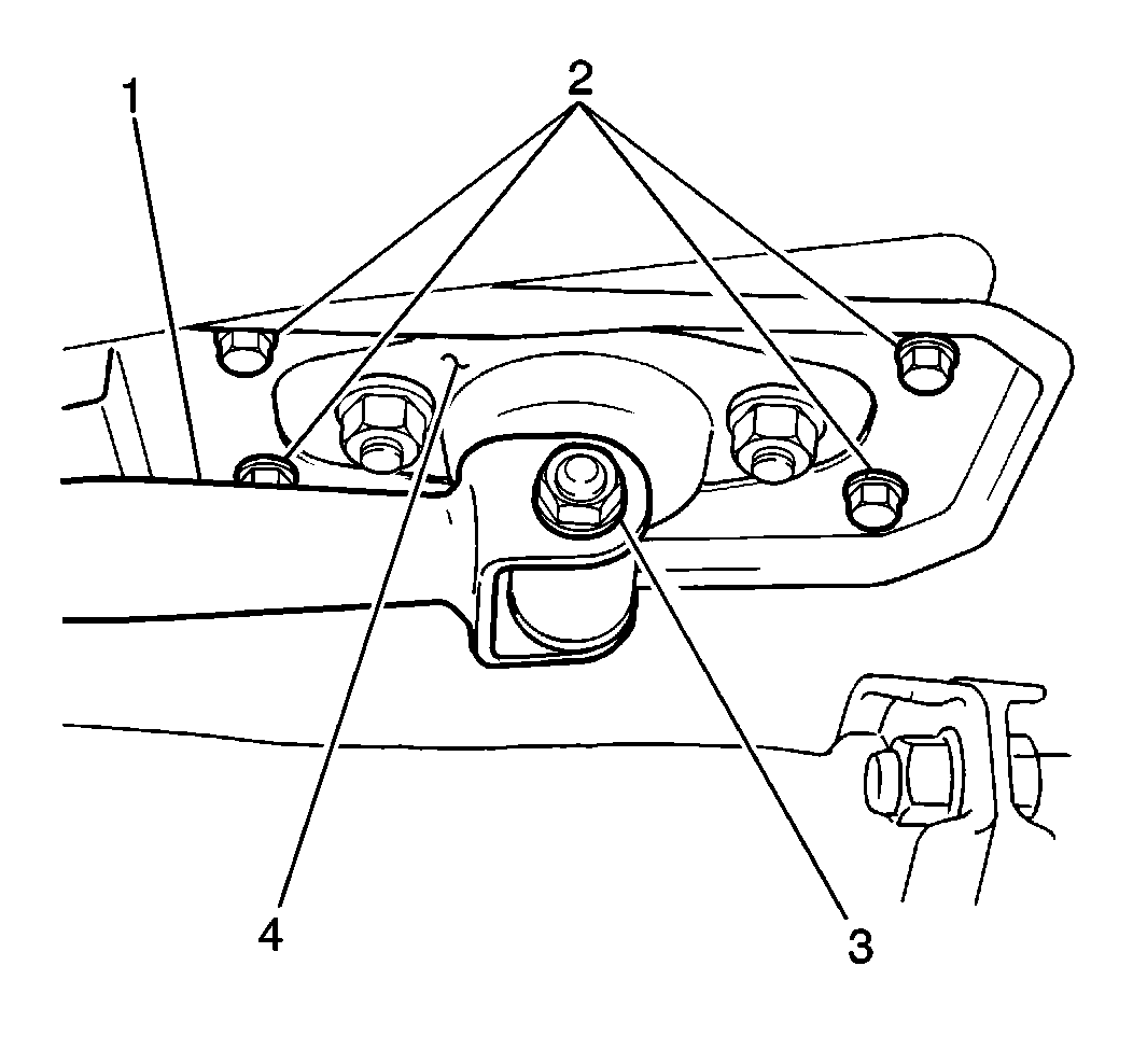
| • | The 4 gearshift control lever guide plate bolts (2) |
| • | The extension rod |
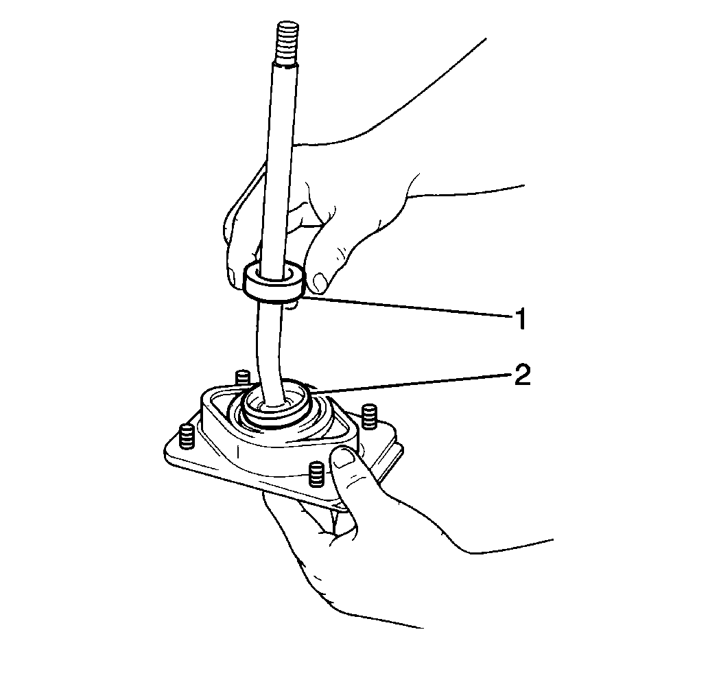
| • | The gearshift control lever snap ring |
| • | The gearshift control lever shim |
| • | The gearshift control lever upper seat (1) |
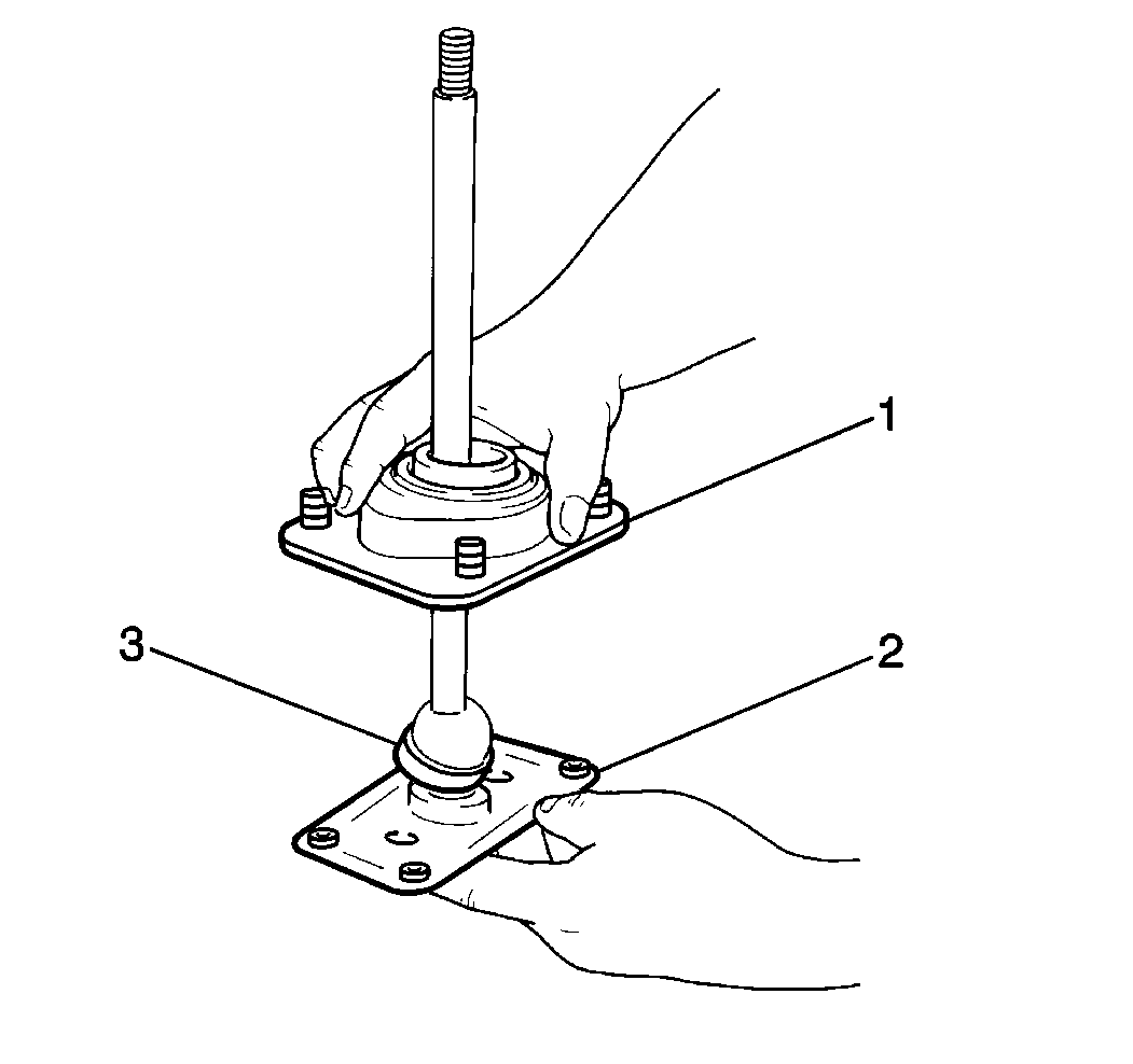
| • | Two gearshift control lever housing-to-guide plate nuts |
| • | Two washers |
| • | The gearshift control lever housing (1) |
Installation Procedure
- Inspect the control lever components for excessive wear or damage.
- Install the gearshift control lever lower seat (3) to the gearshift control lever.
- Install the gearshift control lever housing (1) to the gearshift control lever guide plate (2).
- Install the gearshift control lever upper seat (1) and the shim into the gearshift control lever housing.
- Install the gearshift control lever lower boot onto the gearshift control lever.
- Install the gearshift control lever boot cover onto the gearshift control lever.
- Install the gearshift control lever (1) into the vehicle.
- Install the extension rod to the gearshift control lever guide plate (4).
- Install the gearshift control shaft to the gearshift control lever.
- Lower the vehicle.
- Install four gearshift control lever housing nuts to the gearshift control lever housing studs.
- Measure the distance from the gearshift control lever knob (2) to the instrument panel (1) with the gearshift control lever in the NEUTRAL position.
- If the gearshift control, lever is not at the correct distance from the instrument panel, move the control lever forward or backward in order to obtain the proper distance.
- Secure the gearshift control lever housing nuts.
- Measure the gearshift control lever vertical play.
- If the gearshift control lever vertical play exceeds 0.2 mm (0.0007 in), replace the existing shim with a larger shim. Refer to Transmission Specifications .
- Install the console into the vehicle.
- Install the gearshift control lever upper boot to the gearshift control lever.
- Apply a light coat of GM P/N 12345493 or the equivalent to the threaded portion of the gearshift control lever.
- Screw the gearshift control lever knob on clockwise in order to install the gearshift control lever knob to the gearshift control lever.

Replace the components as necessary.
Notice: Use the correct fastener in the correct location. Replacement fasteners must be the correct part number for that application. Fasteners requiring replacement or fasteners requiring the use of thread locking compound or sealant are identified in the service procedure. Do not use paints, lubricants, or corrosion inhibitors on fasteners or fastener joint surfaces unless specified. These coatings affect fastener torque and joint clamping force and may damage the fastener. Use the correct tightening sequence and specifications when installing fasteners in order to avoid damage to parts and systems.
Use the following components in order to secure the gearshift control lever housing (1).
| • | Two washers |
| • | Two gearshift control lever housing-to-guide plate nuts |
Tighten
Tighten the gearshift control lever housing-to-guide plate nuts to 40 N·m (29 lb ft).

Use the control lever snap ring in order to secure the gearshift control lever upper seat and shim.
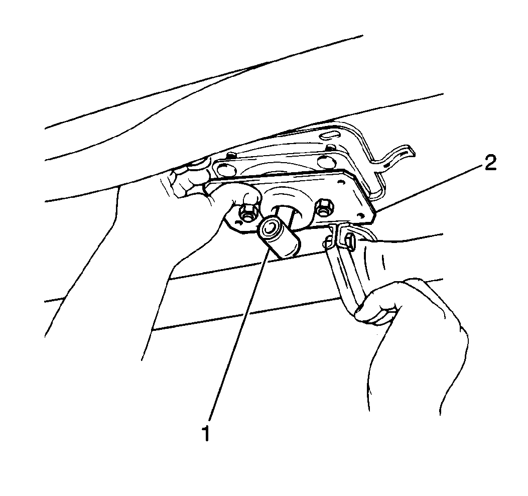

Use four gearshift control lever guide plate bolts (2) in order to secure the extension rod.
Tighten
Tighten the gearshift control lever guide plate bolts (2) to 10 N·m (89 lb in).
Use the gearshift control shaft rear through bolt and nut in order to secure the gearshift control shaft.
Tighten
Tighten the gearshift control shaft rear through bolt and nut to 20 N·m (15 lb ft).
Do NOT fully tighten the nuts.
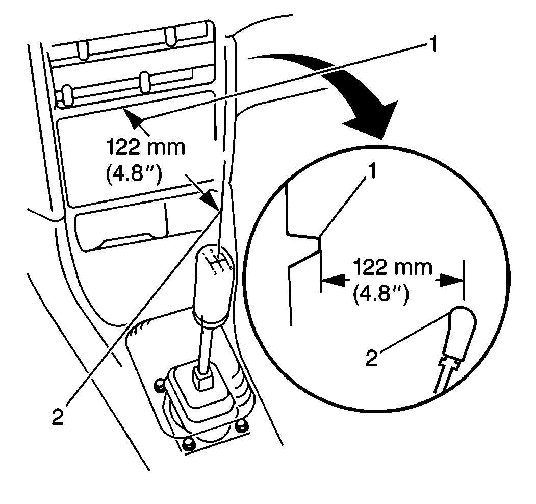
The distance should measure 122 mm (4.8 in).
Tighten
Tighten the gearshift control lever housing nuts to 6 N·m (53 lb in).
The vertical play should measure no more than 0.2 mm (0.0007 in).
Use six screws in order to secure the console.
