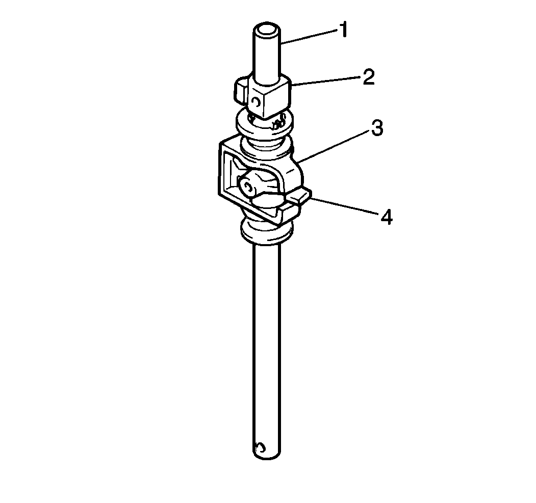
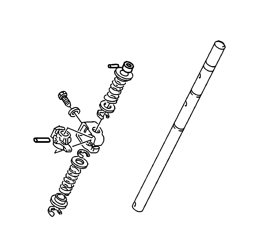
- Install one C-clip onto the gearshift and select shaft.
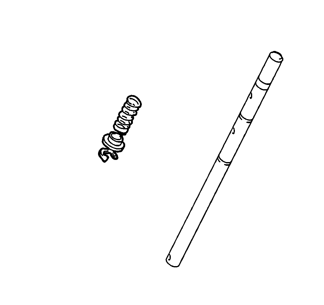
- Install the select spring guide and the low speed
select spring onto the gearshift and select shaft.
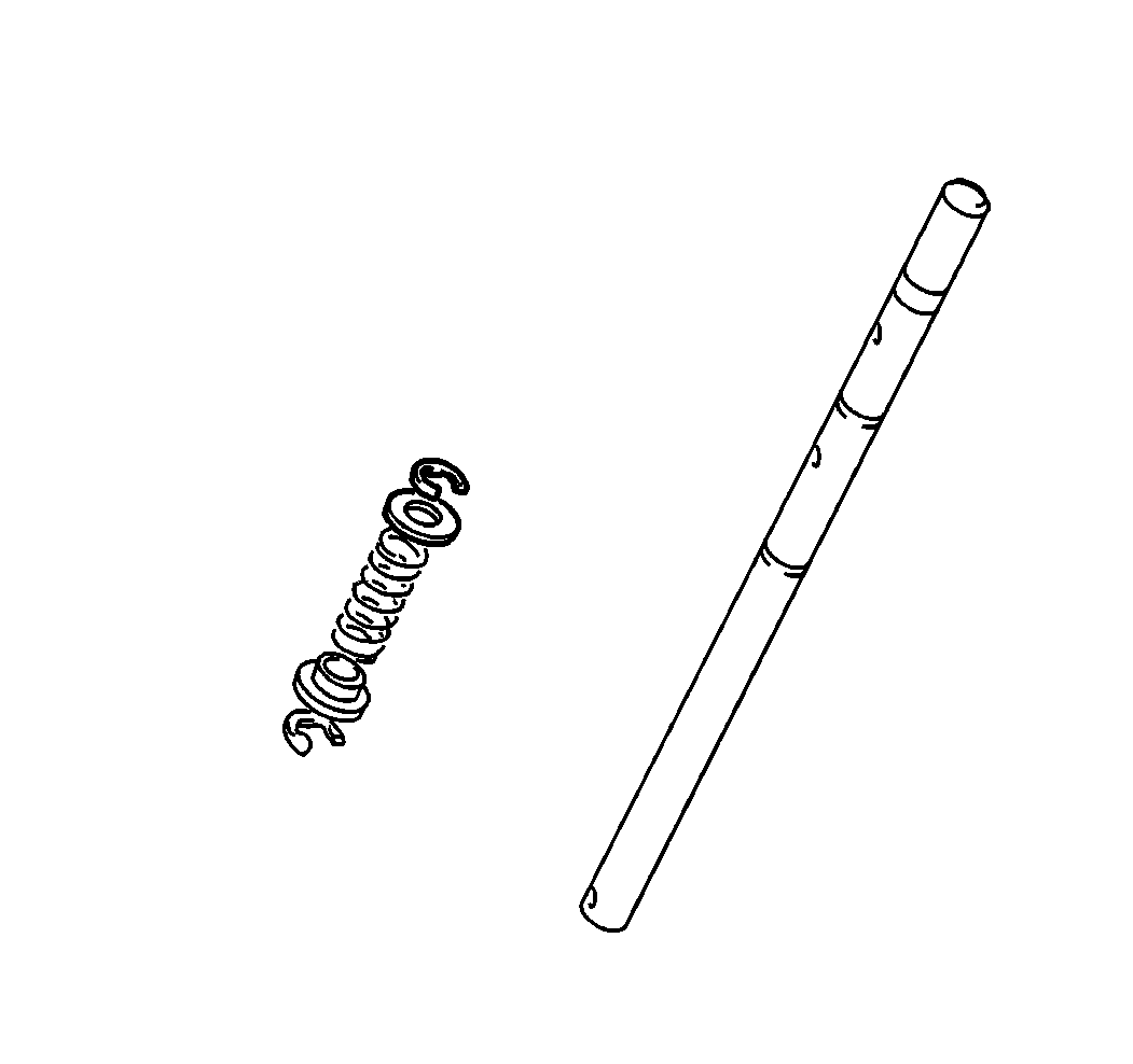
- Install one washer and one C-clip onto the gearshift
and select shaft.
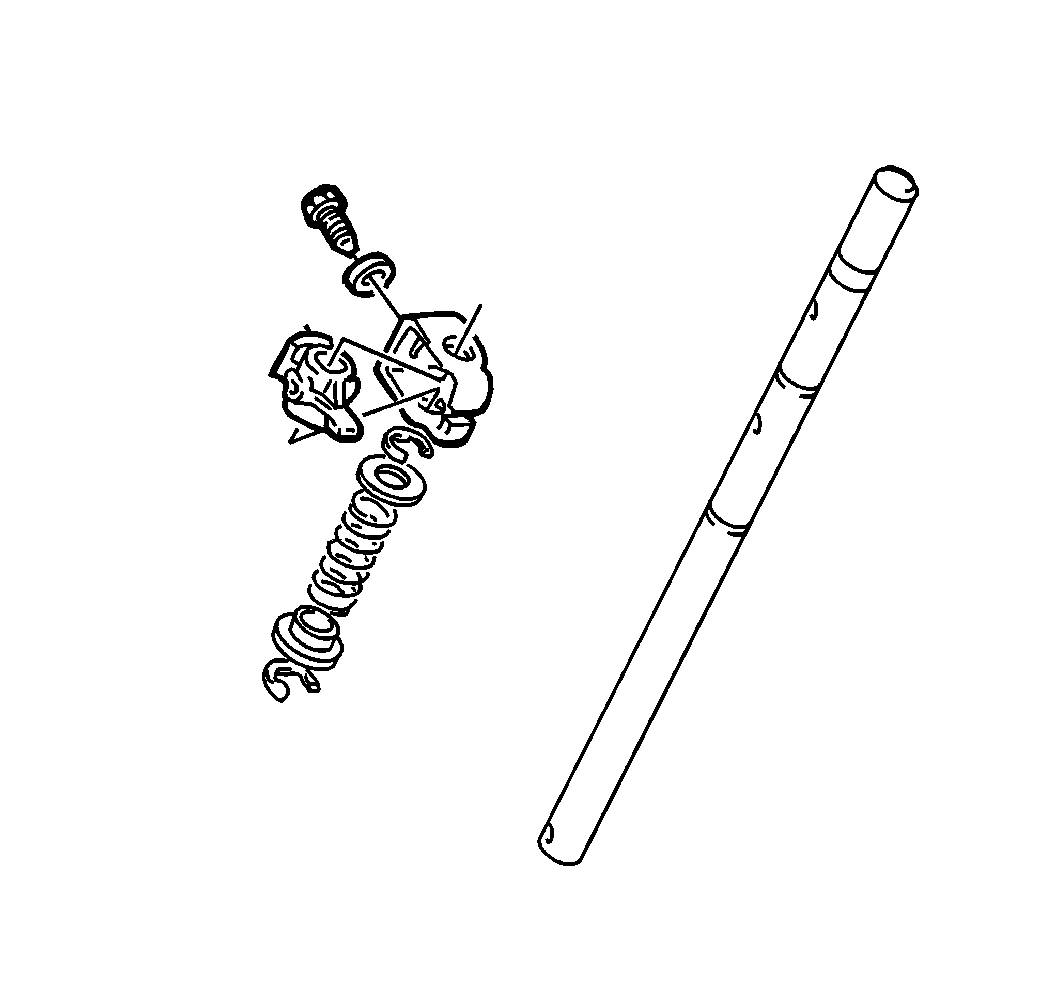
- Install the gearshift interlock plate and gearshift
and select lever onto the gearshift and select shaft.
- Install the fifth and reverse gearshift cam inner and outer roll pins
into the gearshift and select shaft using a standard drift punch and
a hammer.
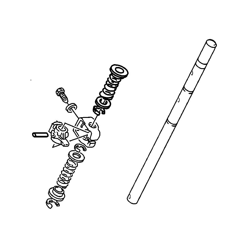
- Install one C-clip and one washer onto the gearshift
and select shaft.
- Install the reverse select spring and select spring guide onto the gearshift
and select shaft.
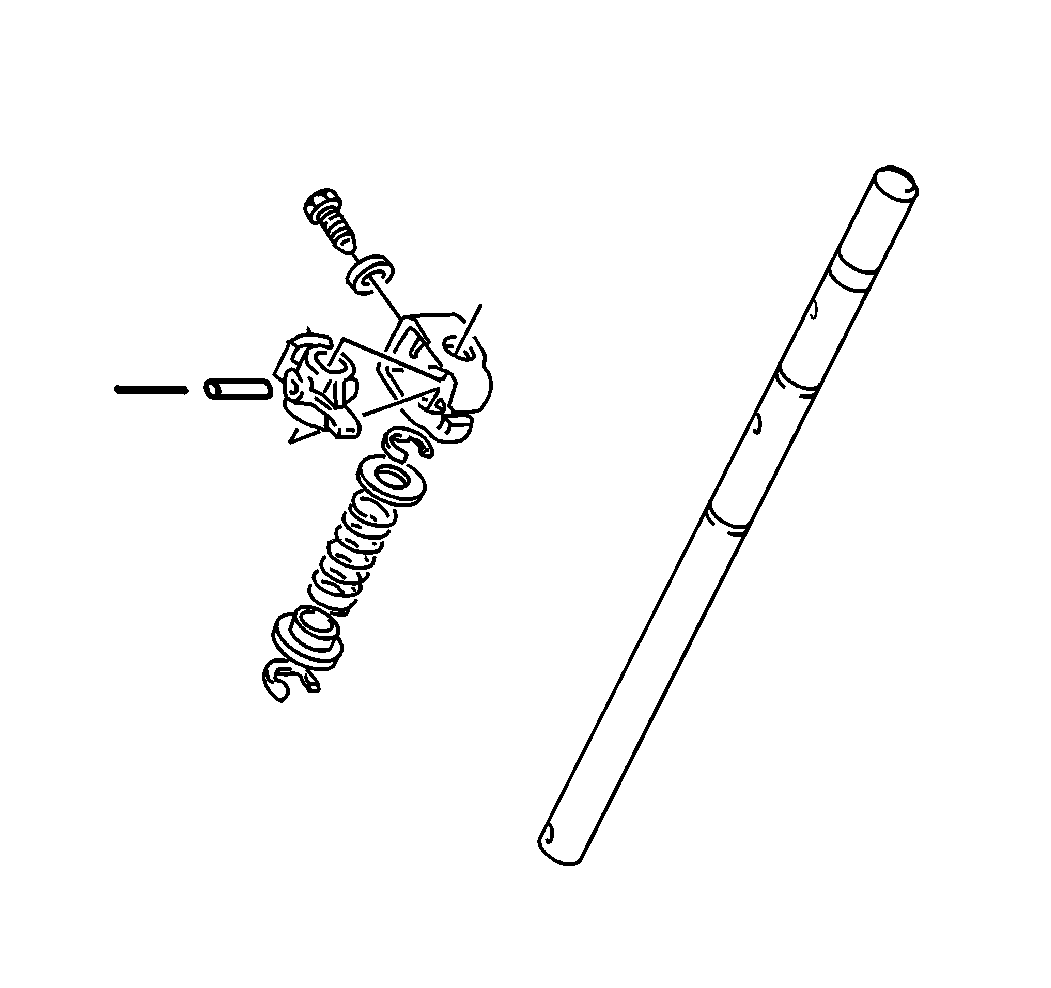
- Install the fifth and reverse gearshift cam guide
onto the gearshift and select shaft.
- Install the gearshift cam guide roll pin into the gearshift and select
shaft using a standard drift punch and a hammer.
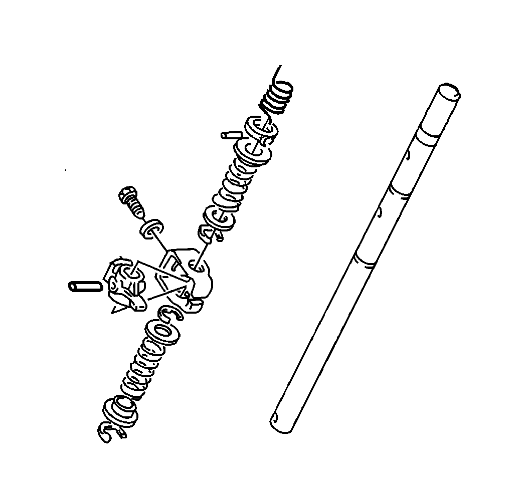
- Install the fifth and reverse cam guide return spring
onto the gearshift and select shaft.
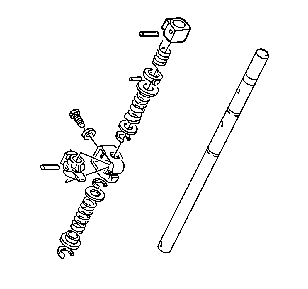
Important: When installing the fifth and reverse gearshift
cam, load the fifth and reverse cam guide return spring by winding it one-half to
one full turn.
- Install the fifth and reverse gearshift cam onto the gearshift and select shaft.
- Install the reverse interlock shaft roll pin into the gearshift and select
shaft using a standard drift punch and a hammer.
Notice: Use the correct fastener in the correct location. Replacement fasteners
must be the correct part number for that application. Fasteners requiring
replacement or fasteners requiring the use of thread locking compound or sealant
are identified in the service procedure. Do not use paints, lubricants, or
corrosion inhibitors on fasteners or fastener joint surfaces unless specified.
These coatings affect fastener torque and joint clamping force and may damage
the fastener. Use the correct tightening sequence and specifications when
installing fasteners in order to avoid damage to parts and systems.
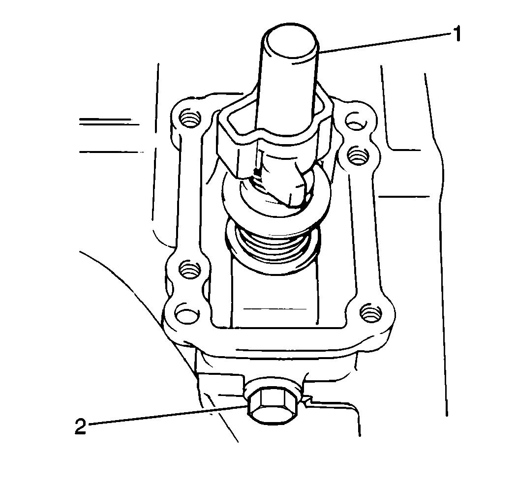
- Install the following items into the left case:
| • | The gearshift and select shaft assembly (1) |
| • | The gearshift interlock bolt (2) and washer |
Tighten
Tighten the gearshift interlock bolt to 28 N·m
(21 lb ft).
- Raise and suitably support the vehicle. Refer to Lifting and Jacking the
Vehicle in General Information.
- Align the gearshift and select shaft assembly bolt hole with the gearshift
yoke bolt hole.
- Apply GM P/N 12345493, or equivalent, to the threaded portion
of the gearshift yoke bolt hole.
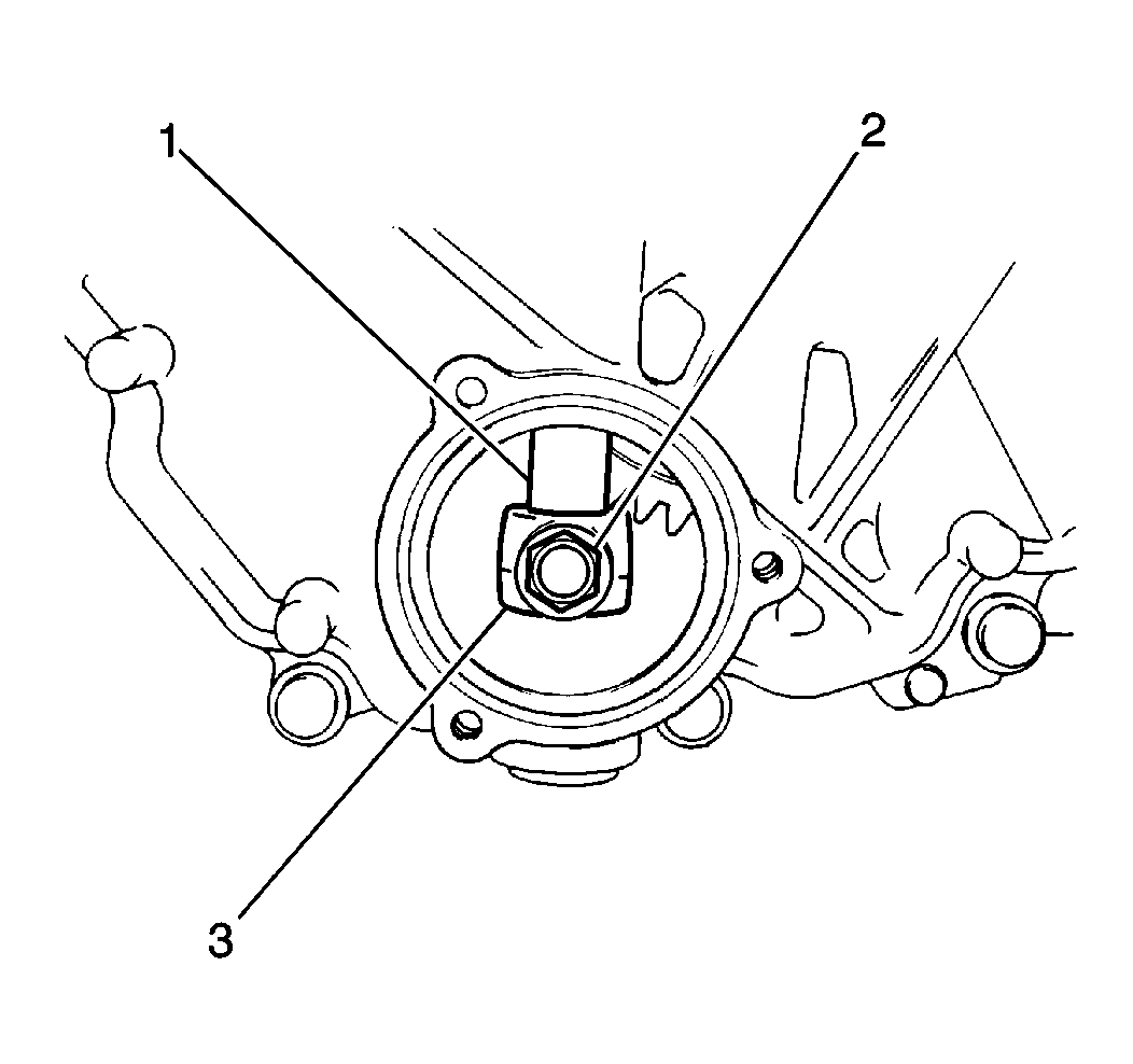
- Install the gearshift yoke bolt (2) into the
gearshift yoke (3).
Tighten
Tighten the gearshift yoke bolt to 28 N·m
(21 lb ft).
- Inspect the left case cover O-rings for cuts or damage. Replace if necessary.
- Install the left case cover O-rings.
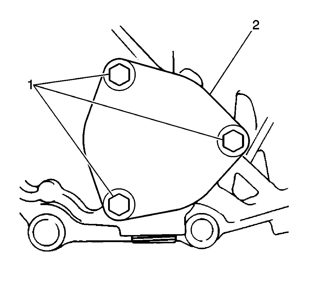
- Install the left case cover (2).
Tighten
Tighten 3 left case cover bolts (1)
to 12 N·m (106 lb in).
- Apply GM P/N 12346004, or equivalent, to the threaded portion
of the transaxle drain plug.
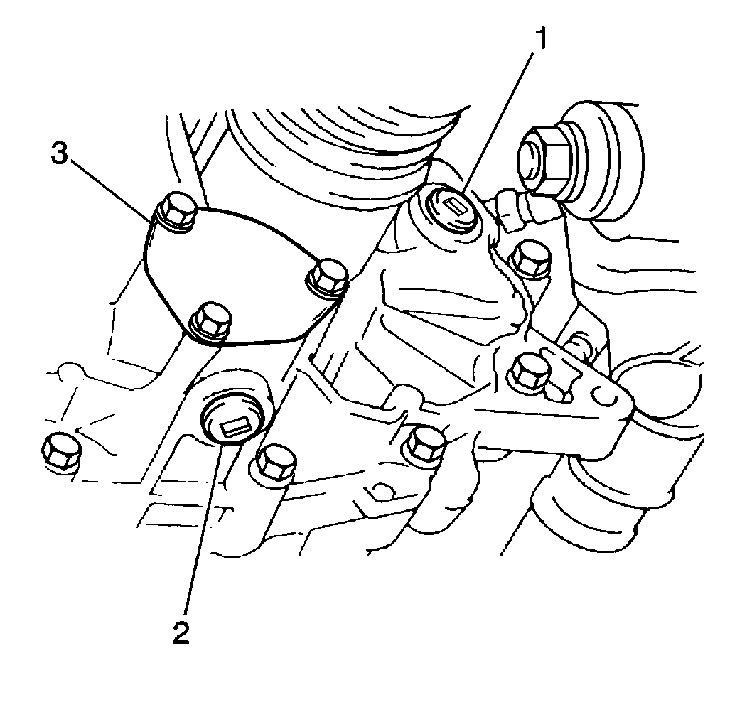
- After the transaxle has completely drained, install
the transaxle drain plug (2).
- Add approximately 2.4 liters (2.5 qts) of Castrol®
Syntorq Transmission Fluid GM P/N 12346190, or the equivalent, into
the transaxle oil level/filler plug hole (1). The oil level should
be even with the bottom of the transaxle plug hole.
- Apply GM P/N 12346004, or the equivalent, to the transaxle oil
level/filler plug threads.
- Install the transaxle oil level/filler plug into the transaxle.
Tighten
Tighten the transaxle oil level/filler plug to 21 N·m
(15 lb ft).
- Lower the vehicle.
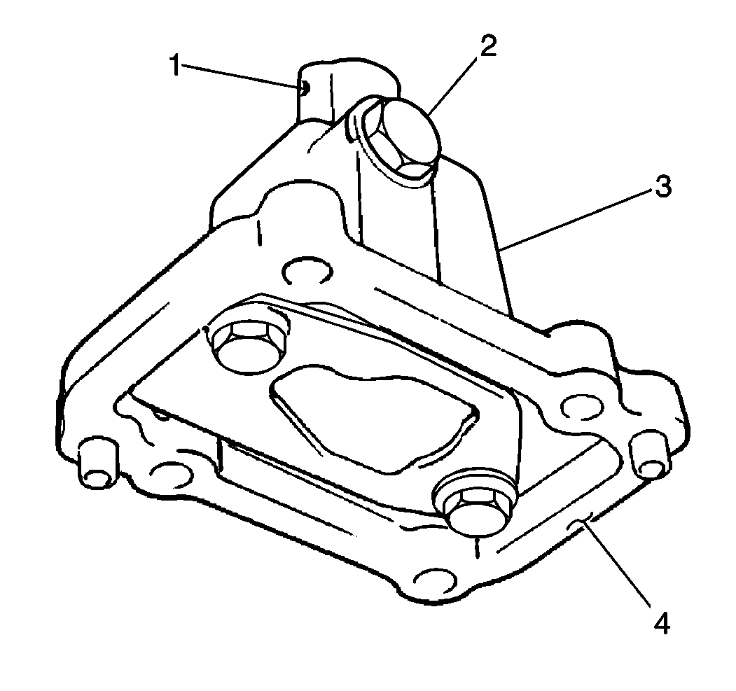
- Clean the gearshift guide case (3) mating surfaces (4).
- Apply GM P/N 12346240, or the equivalent, to the gearshift guide
case mating surfaces.
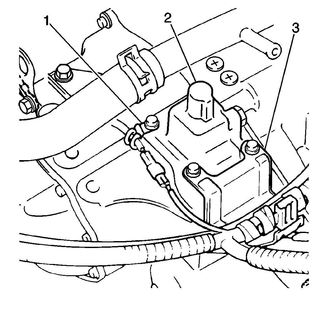
- Install the gearshift guide case (2) to the
transaxle.
- Install the retaining clamp (1) and the engine wiring harness bracket (3)
to the gear shift guide case.
Tighten
Tighten the 4 gearshift guide case bolts
to 12 N·m (106 lb in).


