SERVICE MANUAL UPDATE SEC. 7A A/T LINE PRESSURE TESTS

Subject: LINE AND GOVERNOR PRESSURE TESTS
Model and Year: 1989-91 GEO PRIZM WITH AUTOMATIC TRANSMISSION
LINE AND GOVERNOR PRESSURE TESTS
This bulletin covers diagnostic service procedures for line pressure and governor pressure tests on Base model GEO Prizm vehicles equipped with the A131L 3-speed automatic transaxle. These procedures supplement Automatic Transaxle - General Description and On-Vehicle Service (Section 7A) and A131L Automatic Transaxle - General Description and On-Vehicle Service (Section 7A-A-1) of the 1989/1990 and 1991 GEO Prizm Service Manuals (ST373-89/90 and ST373-91) respectively.
Diagnosis
Line Pressure Test
Figures 1 through 4
Tools Required:
J 35752 Oil Pressure Gauge Adapter J 21867 Universal Pressure Gauge Set
IMPORTANT
* This test should only be performed at a normal operating fluid temperature of 70 degrees to 80 degrees C (1 58 to 176 degrees F).
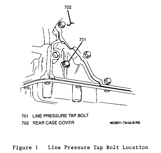
1. Raise and suitably support vehicle. Refer to General information (Section 0A) of the 1991 GEO Prizm Service Manual (ST373-91). 2. Remove six bolts and left splash shield. 3. Remove the line pressure tap bolt from the rear of the transaxle (Figure 1).
Figure 1 - Line Pressure Tap Bolt Location
4. Install a J 35752 oil pressure gauge adapter into the line pressure tap on the rear of the transaxle. 5. Install a J 21867 universal pressure gauge set into the J 35752 oil pressure gauge adapter. 6. Lower vehicle. 7. Route the J 21867 universal pressure gauge set over the front fender and through the driver's window so that it can be read from the passenger compartment. 8. Connect a tachometer so that it can be read from the passenger compartment. 9. Apply parking brake and block vehicle wheels. 10. Depress brake pedal fully and start engine.
CAUTION:
FOR STEPS 11 THROUGH 14, PROCEDURES FOR TESTING LINE PRESSURE AT IDLE AND STALL SPEEDS, THE BRAKE PEDAL MUST BE FULLY DEPRESSED THROUGHOUT THE MEASUREMENT PROCEDURE. FAILURE TO DO SO COULD RESULT IN PERSONAL INJURY AND/OR PROPERTY DAMAGE.
11. Place selector lever in "D" range and record line pressure at idle speed (600 to 800 rpm).
NOTICE: DO NOT RUN ENGINE AT STALL SPEED FOR MORE THAN FIVE SECONDS CONTINUOUSLY OR ENGINE OIL TEMPERATURES MAY BECOME EXCESSIVELY HIGH.
12. Depress accelerator pedal fully (wide open throttle) and record line pressure in "D" range at stall speed (2,050 to 2,350 rpm). Release accelerator pedal. 13. Keeping brake pedal fully depressed, place selector lever in "R" range and record line pressure at idle speed (600 to 800 rpm). 14. Depress accelerator pedal fully (wide open throttle) and record line pressure in "R" range at stall speed (2,050 to 2,350 rpm). Release accelerator pedal. 15. Place the selector lever in "P" range and turn ignition switch to "LOCK". 16. Remove the tachometer from the vehicle. 17. Remove the J 21867 universal gauge set from the passenger compartment. 18. Raise and suitably support vehicle. Refer to General Information (Section 0A) of the 1991 GEO Prizm Service Manual (ST373-91). 19. Remove the J 21867 universal pressure gauge set from the J 35752 oil pressure gauge adapter. 20. Remove the J 35752 oil pressure gauge adapter from the line pressure tap on the rear of the transaxle. 21. Install the line pressure tap bolt into the rear of the transaxle.
Tighten o Line pressure tap bolt to 12 N.m. (106 lbs. in.).
22. Install the left splash shield and secure with six bolts.
Tighten o Splash shield bolts to 12 N.m. (106 lbs. in.).
23. Lower vehicle.
Evaluation
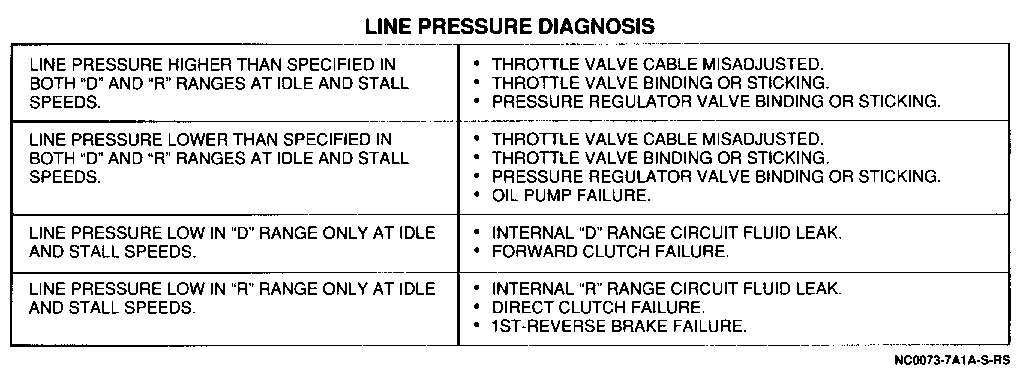
Compare line pressure test results with the "Line Pressure Test Results" chart (Figure 2). If line pressure is not as specified, refer to the "Line Pressure Diagnosis" chart for further evaluation (Figure 3).
Figure 2 Line Pressure Test Results Figure 3 Line Pressure Diagnosis
Governor Pressure Test
Figures 1, 4. 5 and 6
Tools Required:
J 35752 Oil Pressure Gauge Adapter J 21867 Universal Pressure Gauge Set
IMPORTANT: This test should only be performed at a normal operating fluid temperature of 70 to 80 degrees C (158 to 176 degrees F).
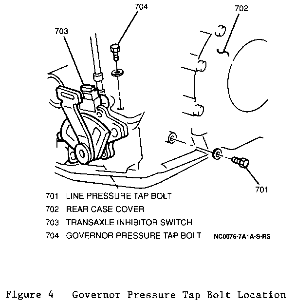
1. Raise and suitably support vehicle. Refer to General Information (Section 0A) of the 1991 GEO Prizm Service Manual (ST373-91). 2. Remove six bolts and left splash shield. 3. Remove the governor pressure tap bolt (next to the transaxle inhibitor switch) (Figure 4).
Figure 4 Governor Pressure Tap Bolt Location
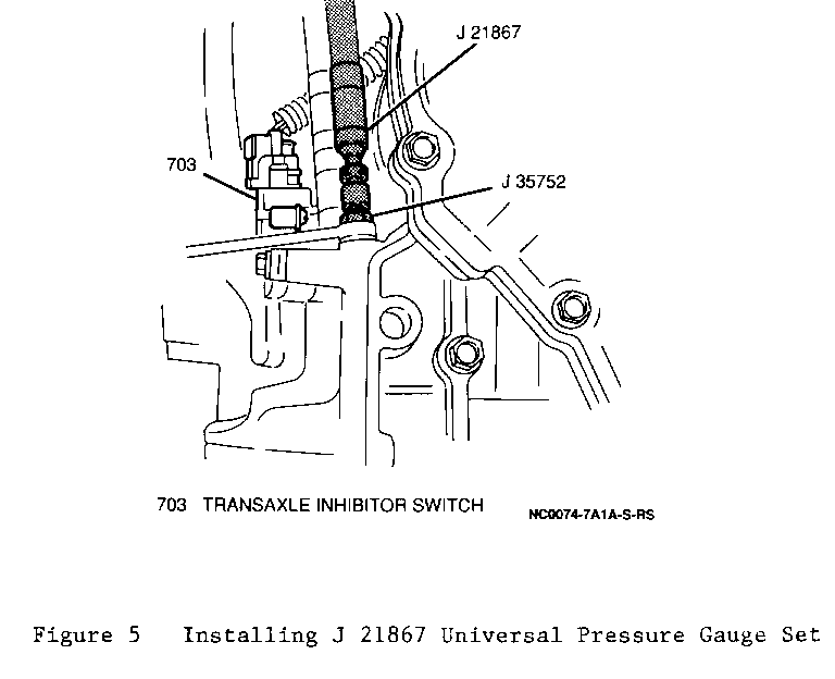
4. Install a J 35752 oil pressure gauge adapter into the governor pressure tap (next to the transaxle inhibitor switch). 5. Install a J 21867 universal pressure gauge set into the J 35752 oil pressure gauge adapter (Figure 5).
Figure 5 Installing J 21867 Universal Pressure Gauge
6. Lower vehicle. 7. Route the J 21867 universal pressure gauge set over the cowl panel and in through the passenger door window so that it can be read from the passenger compartment. 8. Road test the vehicle at the speeds specified in the "Governor Pressure" chart (Figure 6) while another technician monitors and records governor pressure.
Figure 6 Governor Pressure
9. Remove the J 21867 universal pressure gauge set from the passenger compartment. 10. Raise and suitably support vehicle. Refer to General Information (Section 0A) of the 1991 GEO Prizm Service Manual (ST373-91). 11. Remove the J 21867 universal pressure gauge set from the J 35752 oil pressure gauge adapter. 12. Remove the J 35752 oil pressure gauge adapter from the governor pressure tap (next to the transaxle inhibitor switch). 13. Install the governor pressure tap bolt (next to the transaxle inhibitor switch).
Tighten o Governor pressure tap bolt to 12 N.m. (1 06 lbs. in.).
14. Install the left splash shield and secure with six bolts.
Tighten o Splash shield bolts to 12 N.m. (1 06 lbs. in.).
15. Lower vehicle
Evaluation
If governor pressures are within the tolerances allowed on the "Governor Pressure" chart (Figure 6), the governor is operating properly. If the governor pressures are not within the tolerances allowed, one of the following possibilities exists:
o Incorrect line pressure. o Governor valve binding or sticking. o Internal governor fluid circuit leak.
Figure 2 Line Pressure Test Results:(Refer to images.) ------------------------------------ LINE PRESSURE TEST RESULTS ================================================================= ENGINE RPM RANGE LINE PRESSURE ---------------- ------ ------------------------ IDLE SPEED "D" 365-421 kPa (53-61 psi) 600 - 800 RPM - "R" 627-703 kPa (91-102 psi)
STALL SPEED "D" 958-1,048 kPa (139-152 psi) 2,050 - 2,350 RPM "R" 1,413-1,524 kPa (205-221 psi)
Figure 3 Line Pressure Diagnosis: (Refer to images.) --------------------------------- LINE PRESSURE DIAGNOSIS ======================== LINE PRESSURE HIGHER THAN o THROTTLE VALVE CABLE MISADJUSTED. SPECIFIED IN BOTH "D" AND "R" o THROTTLE VALVE BINDING OR STICKING. RANGES AT IDLE AND STALL o PRESSURE REGULATOR VALVE BINDING SPEEDS. OR STICKING.
LINE PRESSURE LOWER THAN o THROTTLE VALVE CABLE MISADJUSTED. SPECIFIED IN BOTH "D" AND "R" o THROTTLE VALVE BINDING OR STICKING. RANGES AT IDLE AND STALL o PRESSURE REGULATOR VALVE BINDING SPEEDS. OR STICKING. o OIL PUMP FAILURE.
LINE PRESSURE LOW IN "D" RANGE o INTERNAL "D" RANGE CIRCUIT FLUID LEAK. ONLY AT IDLE AND STALL SPEEDS. o FORWARD CLUTCH FAILURE.
LINE PRESSURE LOW IN "R" RANGE o INTERNAL "R" RANGE CIRCUIT FLUID LEAK. ONLY AT IDLE AND STALL SPEEDS. o DIRECT CLUTCH FAILURE. o 1ST-REVERSE BRAKE FAILURE.
Figure 6 Governor Pressure: (Refer to images.) --------------------------- GOVERNOR PRESSURE ------------------------------------------------------- VEHICLE SPEED GOVERNOR PRESSURE ---------------- ---------------------- 23 km/h (14 mph) 69-145 kPa (10-21 psi) 45 km/h (28 mph) 131-200 kPa (19-29 psi) 68 km/h (43 mph) 227-303 kPa (33-44 psi)


General Motors bulletins are intended for use by professional technicians, not a "do-it-yourselfer". They are written to inform those technicians of conditions that may occur on some vehicles, or to provide information that could assist in the proper service of a vehicle. Properly trained technicians have the equipment, tools, safety instructions and know-how to do a job properly and safely. If a condition is described, do not assume that the bulletin applies to your vehicle, or that your vehicle will have that condition. See a General Motors dealer servicing your brand of General Motors vehicle for information on whether your vehicle may benefit from the information.
