For 1990-2009 cars only
Removal Procedure
- Remove the accelerator (1) cable and cruise control cable, if equipped, from the air cleaner (ACL) assembly clip.
- Disconnect the intake air temperature (IAT) sensor electrical connector.
- Disconnect the four cap clips from the ACL.
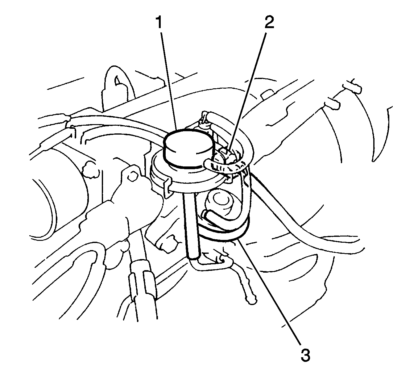
- Disconnect EGR regulator vacuum valve electrical connector (2)
- Disconnect the EGR vacuum hoses from the EGR valve (3).
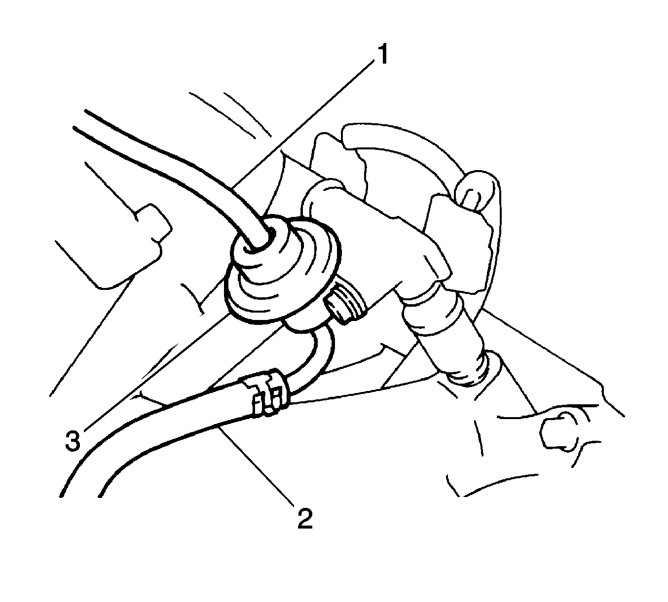
- Remove the one vacuum hose (1) from the fuel pressure regulator (3).
- Remove the one clamp and the positive crankcase ventilation (PCV) hose from the PCV valve.
- Remove the one clamp and the PCV hose from the cylinder head cover.
- Remove the two nuts from the air intake chamber cover and the throttle body assembly.
- Remove the three Allen® head screws from the air intake chamber cover and the throttle body assembly.
- Reposition the air intake chamber cover and the throttle body assembly aside.
- Remove the air intake chamber cover gasket.
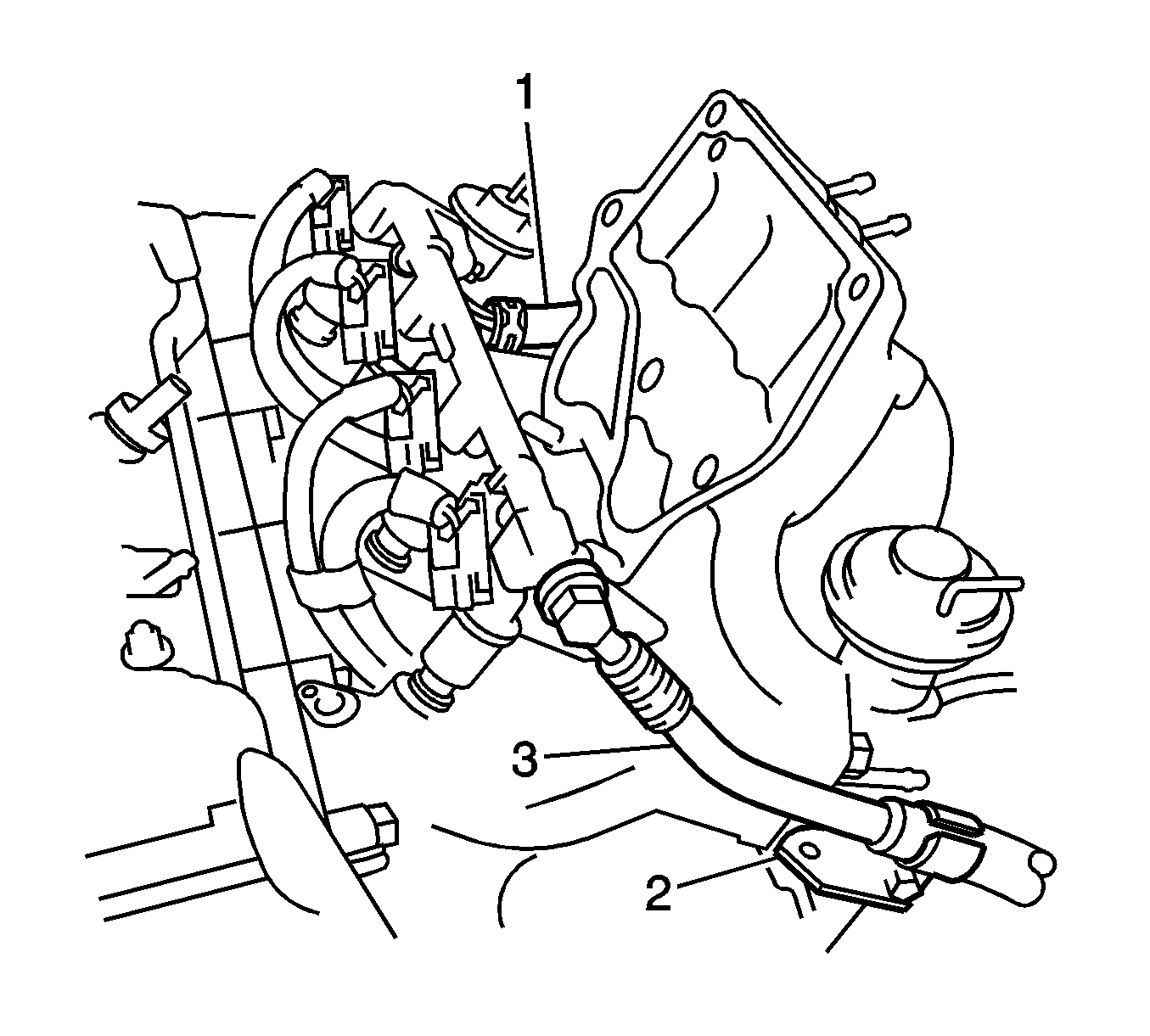
- Disconnect the fuel injector electrical connectors (3).
- Remove the one bolt and the fuel feed inlet hose from the fuel rail.
- Remove the one clamp and the fuel return hose (1) from the fuel pressure regulator.
- Remove the two bolts and the injectors with the fuel rail from the vehicle.
- Remove the four insulators and the two spacers from the intake manifold.
- Remove the four injectors from the fuel rail.
- Remove the O-rings and grommet from each injector.
- Remove the two bolts and the fuel pressure regulator from the fuel rail.
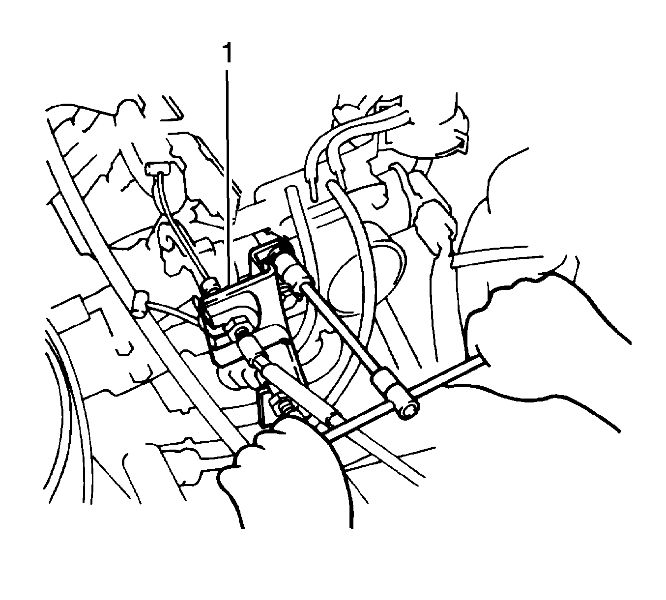
Important: Relieve the fuel system pressure. Refer to Fuel Pressure Relief.
Loosen the air cleaner (ACL) hose clamp bolt on the throttle body.
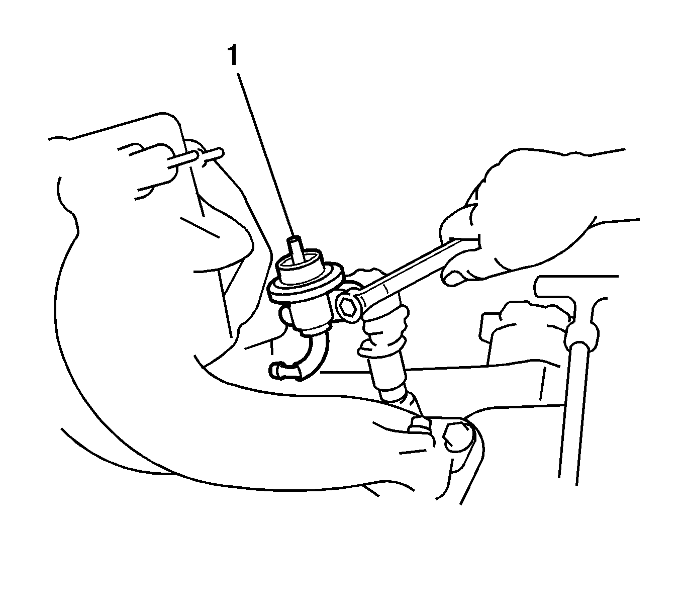
Installation Procedure
- Install the fuel pressure regulator (1) to the fuel rail.
- Secure the fuel pressure regulator with the two bolts.
- Install the new O-rings and grommets to each of the injectors.
- Install the four injectors to the fuel rail, positioning injector connectors upward.
- Install the four new insulators and the two spacers in position on the intake manifold.
- Place the fuel injectors with the fuel rail to the intake manifold.
- Secure the fuel injector and fuel rail with the two bolts.
- Install the fuel feed inlet hose to fuel rail.
- Secure the fuel feed hose with one bolt.
- Install the fuel return hose (1) to the pressure regulator.
- Secure the fuel return hose with one clamp.
- Connect the fuel injector electrical connectors.
- Install the air intake chamber cover and throttle body assembly to the air intake chamber.
- Secure the air intake chamber cover and throttle body assembly with two nuts and three Alllen® head screws.
- Connect one vacuum hose (1) to fuel pressure regulator (3).
- Connect the PCV hose to PCV valve.
- Secure the PCV hose with one clamp.
- Connect the PCV hose to cylinder head cover.
- Secure the PCV hose with one clamp.
- Connect the EGR vacuum regulator valve electrical connector (2).
- Connect the EGR hoses to the EGR valve (3) and pipe.
- Connect the ACL hose and cap to throttle body.
- Install the four cap clips to the ACL.
- Connect the IAT sensor electrical connector.
- Connect the accelerator cable (1) and cruise control cable, if equipped, to ACL assembly clip.

Tighten
Tighten the fuel pressure regulator bolts to 9.3 N·m (82 lb in).
Do not tighten fully.
Check that the fuel injectors rotate smoothly. If the injectors do not rotate smoothly, the probable cause is incorrect installation of the O-rings. Replace the O-rings if necessary and position the injector connector upward.
Tighten
Tighten the fuel rail-to-intake manifold bolts to 15 N·m (11 lb ft).
Tighten
Tighten the fuel feed hose bolt to 29 N·m (22 lb ft).


Tighten
Tighten the ACL hose clamp bolts to 15 N·m (11 lb ft).

