Tool Required
Removal Procedure
- Remove the manual transaxle assembly from the vehicle. Refer to
Transmission Replacement
in Manual Transmission - MB4 and MB5.
- Use the J 35271
in order
to hold the flywheel before removing the bolts.
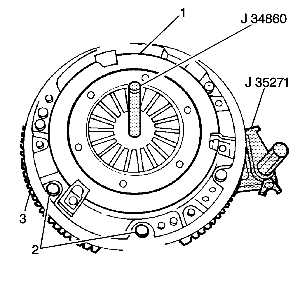
- Slowly and evenly loosen the 6 clutch
pressure plate cover bolts (2) until the clutch pressure plate spring
tension is completely released.
- Remove the 6 clutch pressure plate cover bolts and the
pressure plate from the flywheel.
- Remove the clutch disc from the flywheel.
Important: Index the flywheel (1) in relation to the crankshaft using a
china marker before removal in order to verify correct installation. Poor
engine and/or transaxle balance results if the flywheel is installed
in a position other than the original position.
- Remove the 8 flywheel bolts and the flywheel from the crankshaft.
Note the flywheel position on the crankshaft.
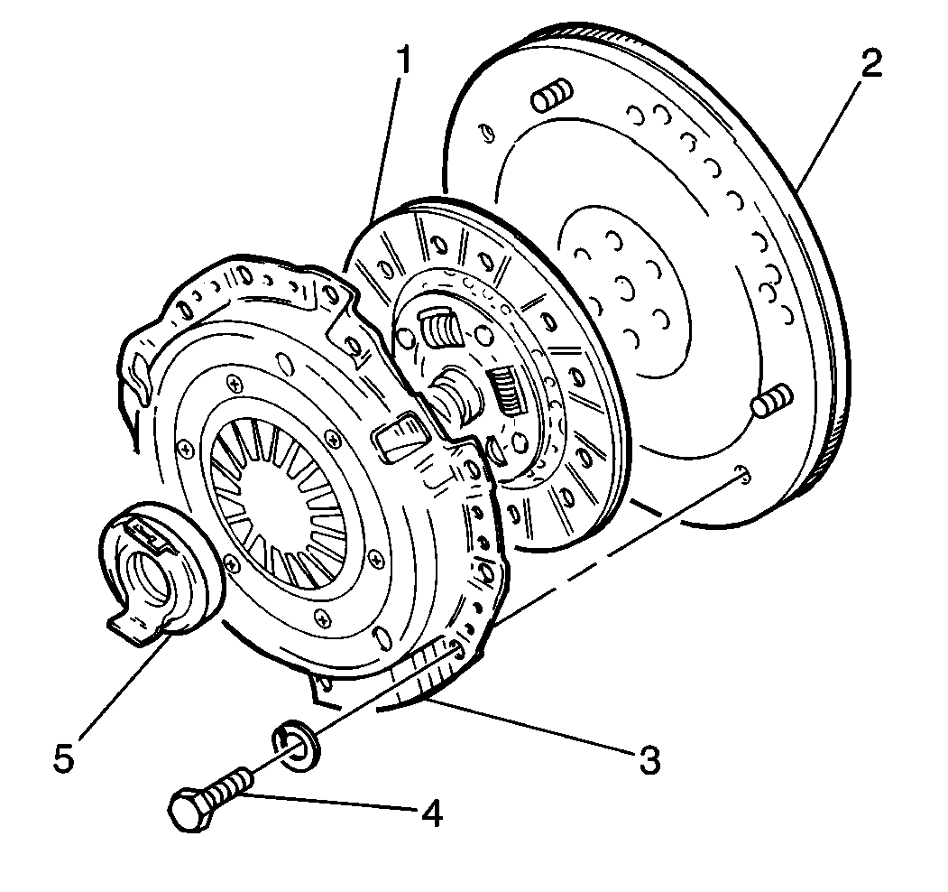
- Clean the flywheel (2) and the
clutch pressure plate-to-clutch disc (1, 3) mating
surfaces of the following substances:
- Clean the clutch disc (1) using a clean dry cloth.
- Inspect the flywheel (2) and the clutch pressure plate (3)
for the following conditions:
| • | Bent or broken pressure plate spring levers |
| • | Weak or damaged diaphragm spring |
Notice: If any of the following conditions exist, do not attempt to disassemble
or repair the clutch pressure plate. If the flywheel or the clutch pressure
plate appears excessively worn, replace the flywheel and/or clutch pressure
plate as necessary.
- Inspect the clutch disc for the following
conditions:
| • | Damaged or weak torsional springs |
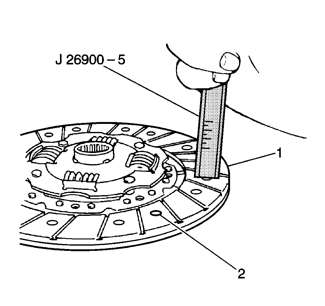
- Use J 26900-5
in order to measure the clutch disc (1) wear. Measure the depth of
each rivet head depression (2). The following specifications
are standard rivet head depth measurements:
- Replace the clutch disc if the clutch rivet depth is less than
0.5 mm (0.02 in).
Installation Procedure
- Install the flywheel to the crankshaft. Align the flywheel-to-engine
marks.
Notice: Apply the proper amount of the sealant to the fastener when assembling
this component. Excessive use of the sealant can prohibit the component from
being assembled properly or allow the fastener to loosen. A component or fastener
that is not assembled properly can loosen or fall off leading to extensive
engine damage.
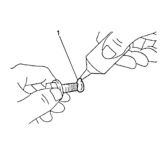
- Apply GM
P/N 12345493, or the equivalent, to the flywheel retaining bolt threads (1).
Notice: Use the correct fastener in the correct location. Replacement fasteners
must be the correct part number for that application. Fasteners requiring
replacement or fasteners requiring the use of thread locking compound or sealant
are identified in the service procedure. Do not use paints, lubricants, or
corrosion inhibitors on fasteners or fastener joint surfaces unless specified.
These coatings affect fastener torque and joint clamping force and may damage
the fastener. Use the correct tightening sequence and specifications when
installing fasteners in order to avoid damage to parts and systems.
- Install the 8 flywheel retaining bolts to the crankshaft.
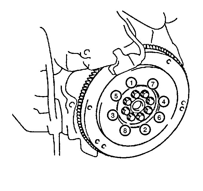
Tighten
Tighten the 8 flywheel retaining bolts in the specified sequence
to 88 N·m (65 lb ft).
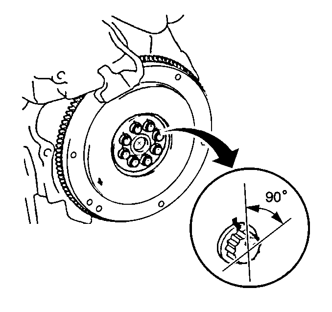
- After the proper torque has been reached,
use J 36660-A
and retighten the flywheel
bolts in the specified sequence an additional 90 degrees.
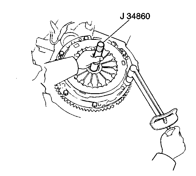
- Install the clutch disc to the flywheel
with the torsion springs offset toward the transaxle. Use the J 34860
in order to center and hold in place
the clutch disc on the flywheel.
- Install the clutch pressure plate to the flywheel. Secure the
flywheel with the 6 clutch pressure plate cover bolts.
Tighten
Tighten the clutch pressure plate cover bolts to 23 N·m
(17 lb ft).
- Remove the J 34860
.
- Lubricate the transaxle input shaft splines and clutch release
bearing using a thin coat of wheel bearing grease GM P/N 1051344 (or
equivalent).
- Install the manual transaxle assembly into the vehicle. Refer
to
Transmission Replacement
in Manual Transmission - MB4 and MB5.


