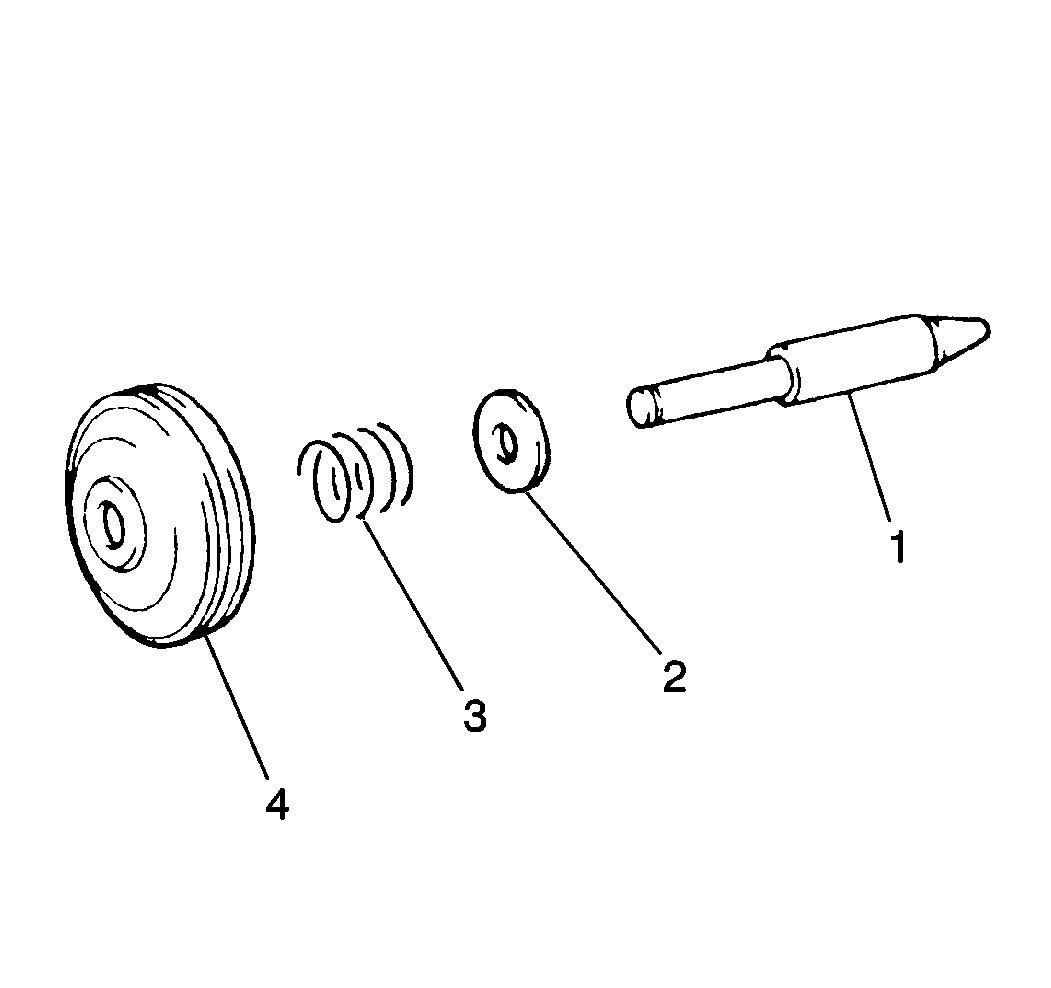
Tools Required
| • | J 36850 Transmission Assembly Lubricant |
Removal Procedure

- Raise and suitably support the vehicle. Refer to Lifting and Jacking the Vehicle in General Information.
- Remove the 6 left splash shield bolts and the left splash shield.
- Remove the 1 bolt from the fluid cooler outlet pipe bracket.
- Install the J 35534
to the transaxle case using the fluid cooler outlet pipe bracket bolts and tighten the J 35534
until the 2nd coast brake cover snap ring can be
removed.
- Remove the following from the transaxle:
| 5.1. | The 2nd coast brake servo snap ring |
| 5.2. | The 2nd coast brake servo cover |
| 5.4. | The 2nd coast brake piston (4) and the outer spring (3) from the piston rod (1) |
- Clean all servo components with solvent and dry thoroughly.
- Inspect the servo bore for minor nicks, scars or other damage.
| • | Remove minor nicks or scars with ultra-fine emery cloth. |
| • | Replace transaxle case if deep nicks or scars are found. |
- Inspect all servo components for minor nicks, scars or other damage.
| • | Remove minor nicks or scars with ultra-fine emery cloth. |
| • | Replace transaxle case if deep nicks or scars are found. |
Installation Procedure

- Apply J 36850
to the 2nd coast brake servo piston seal.
- Install the following to the transaxle:
| 2.1. | The 2nd coast brake outer spring (3) and the piston (4) into the piston rod (1) |
| 2.2. | The piston rod into the transaxle |
| 2.3. | Apply J 36850
to the 2nd coast brake servo cover seals |
| 2.4. | The 2nd coast brake servo cover |
| 2.6. | The 2nd coast brake servo snap ring |
Notice: Use the correct fastener in the correct location. Replacement fasteners
must be the correct part number for that application. Fasteners requiring
replacement or fasteners requiring the use of thread locking compound or sealant
are identified in the service procedure. Do not use paints, lubricants, or
corrosion inhibitors on fasteners or fastener joint surfaces unless specified.
These coatings affect fastener torque and joint clamping force and may damage
the fastener. Use the correct tightening sequence and specifications when
installing fasteners in order to avoid damage to parts and systems.
- Install the fluid cooler outlet pipe bracket bolts.
Tighten
Tighten the bolts to 5 N·m (44 lb in).
- Install the left splash shield bolts.
Tighten
Tighten the left splash shield bolts to 5 N·m (44 lb in).
- Inspect the transaxle fluid level and refill the transaxle as necessary. Refer to
Transmission Fluid Check
.


