Removal Procedure
- Disconnect the negative (-) battery cable.
- Flush the transmission. Refer to Transmission Fluid Cooler Flushing .
- Remove the battery. Refer to Battery Replacement.
- Remove the Intake Air Temperature (IAT) sensor electrical connector from IAT sensor.
- Remove the Air Cleaner (ACL) cover and the ACL filter from the ACL.
- Loosen the ACL intake tube clamp.
- Remove the 3 bolts and ACL from the vehicle.
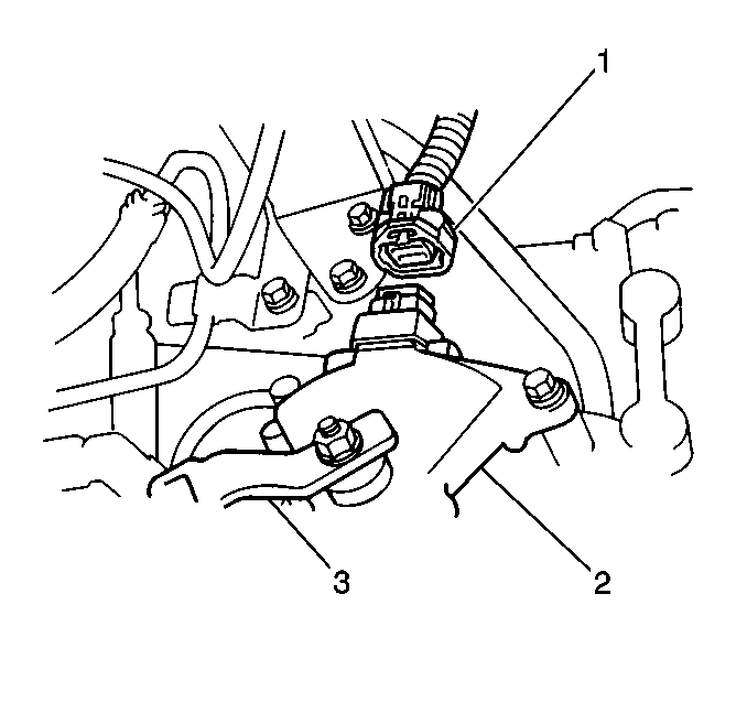
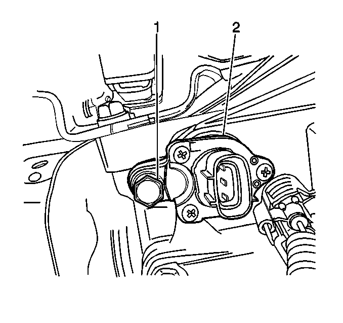
- Remove the PNP switch electrical connector (1) from the PNP switch.
- Remove the 1 bolt and ground strap from the transaxle case.
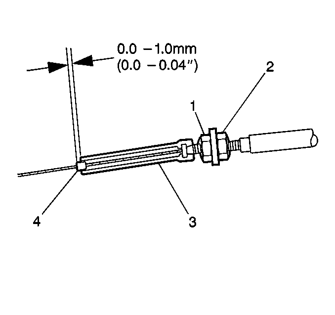
- Loosen the TV cable locknut and adjust the nut.
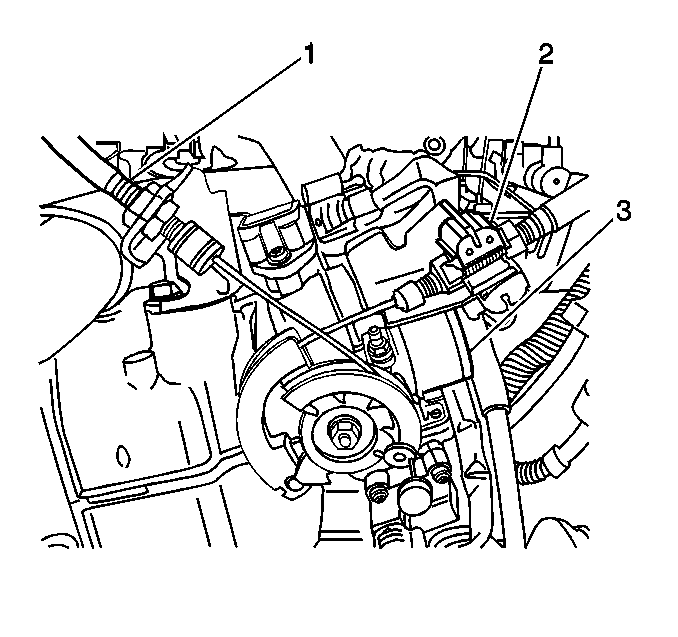
- Remove the TV cable from the throttle linkage and TV cable bracket (1).
- Remove the VSS electrical connector from the VSS.
- Remove the 1 nut, the 1 lock washer and shift select cable from the manual lever.
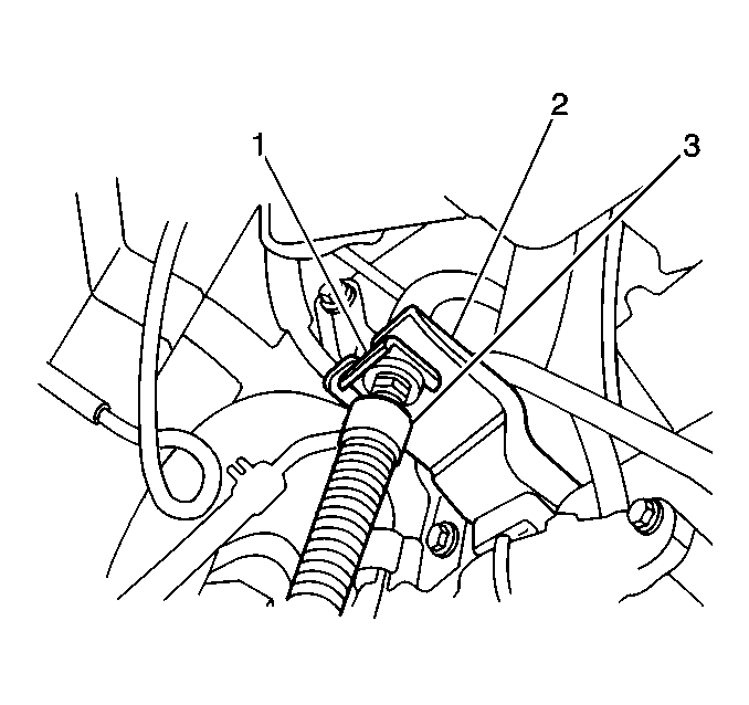
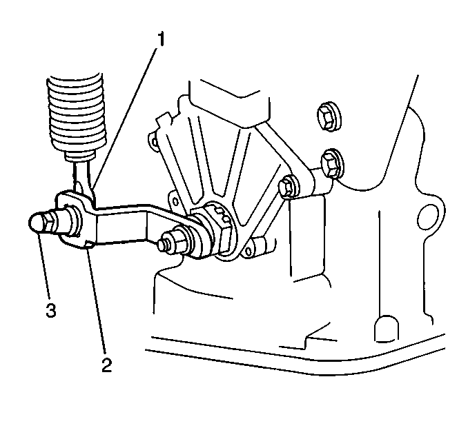
- Remove the E-clip (1) and the shift select cable (3) from the shift select cable bracket (2).
- Remove the 1 bolt and TV cable guide bracket from the transaxle case.
- Remove the 2 upper transaxle-to-engine bolts from the transaxle.
- Remove the starter. Refer to Starter Motor Replacement in Engine Electrical.
- Install the engine support fixture. Refer to Engine Support Fixture in Engine Mechanical - 1.8L.
- Remove the 2 bolts and the left transaxle mounting bracket reinforcement from the transaxle.
- Remove the 1 bolt from the left transaxle mounting bracket.
- Raise and suitably support the vehicle. Refer to Lifting and Jacking the Vehicle in General Information.
- Place a drain pan or a suitable container under the transaxle.
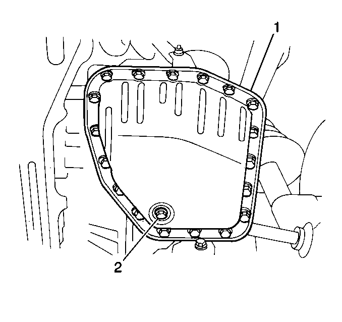
- Remove the transaxle drain plug (2) from the transaxle fluid pan (1) and drain the transaxle fluid.
- Remove the differential filler plug from the differential cover at the rear of the transaxle.
- Remove the differential drain plug from the transaxle case under the differential cover and drain the transaxle fluid from the differential.
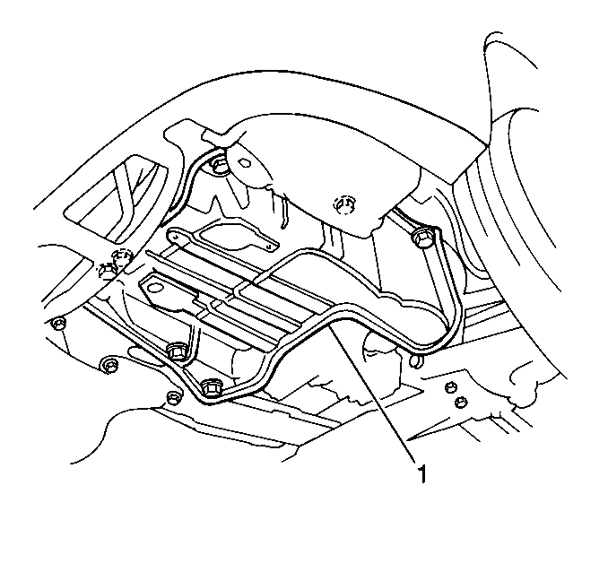
- Remove the 12 bolts and the right and left splash shields (1) from the vehicle.
- Remove the 2 hose clamps and 2 fluid cooler hoses from the inner and the outer fluid cooler pipes at the transaxle.
- Remove the 2 bolts from the left transaxle mounting bracket.
- Remove both front tire and wheel assemblies. Refer to Tire and Wheel Removal and Installation in Tires and Wheels.
- Remove the right and left drive axles from the vehicle. Refer to Wheel Drive Shaft Replacement.
- Remove the 2 bolts from the front transaxle mount.
- Remove the 3 nuts from the rear transaxle mount.
- Remove the front suspension crossmember and the center crossmember from the vehicle. Refer to Crossmember Replacement - Front Suspension.
- Support the transaxle with a suitable hydraulic jack.
- Remove the 5 bolts and lower the engine reinforcement brace from the engine and transaxle.
- Remove the flywheel access cover from the engine rear end plate.
- Remove the 6 flywheel-to-torque converter bolts from the flywheel.
- Remove the drain pan from underneath the transaxle fluid pan.
- Remove the 2 lower transaxle-to-engine bolts from the transaxle.
- Remove the transaxle from the engine by carefully moving the transaxle away from the engine toward the left side of the engine compartment. Very slowly lower the hydraulic jack, verifying that no obstructions exist.
Caution: Unless directed otherwise, the ignition and start switch must be in the OFF or LOCK position, and all electrical loads must be OFF before servicing any electrical component. Disconnect the negative battery cable to prevent an electrical spark should a tool or equipment come in contact with an exposed electrical terminal. Failure to follow these precautions may result in personal injury and/or damage to the vehicle or its components.
Important: Plug the fluid cooler hoses in order to prevent transaxle fluid cooler leakage.
Installation Procedure
- Install the transaxle to the engine by carefully raising the transaxle using a suitable hydraulic jack making sure no obstructions exist.
- Install 2 lower transaxle-to-engine bolts.
- Install the 6 flywheel-to-torque converter bolts into the flywheel.
- Install the flywheel access cover into the engine rear end plate.
- Lower the engine reinforcement brace to the transaxle and the engine. Secure with the 5 bolts.
- Remove the hydraulic jack from under the transaxle.
- Install the front suspension crossmember and the center crossmember to the vehicle. Refer to Crossmember Replacement - Front Suspension.
- Install the 2 bolts into the front transaxle mount.
- Install the 2 bolts into the front transaxle mount.
- Install the right and left drive axles into the vehicle. Refer to Wheel Drive Shaft Replacement.
- Install both front tire and wheel assemblies. Refer to Tire and Wheel Removal and Installation in Tires and Wheels.
- Install the 2 bolts into the left transaxle mounting bracket .
- Install the inner and outer fluid cooler hoses to the inner and outer fluid cooler pipes. Secure the pipes with the 2 clamps.
- Install the right and left splash shields (1) to the vehicle. Secure the shields with the 12 bolts.
- Install the starter. Refer to Starter Motor Replacement.
- Install the differential drain plug into the transaxle case.
- Refill the differential with approximately 1.4 L (1.5 qts) of Dexron®-III Automatic Transmission Fluid GM P/N 12346143, or equivalent, into the differential filler plug hole. The fluid level should be even with the bottom of the differential filler plug hole.
- Install the differential filler plug into the differential cover at the rear of the transaxle.
- Install the transaxle drain plug (2) into the transaxle fluid pan (1).
- Lower the vehicle.
- Install 1 bolt into the left transaxle mounting bracket.
- Install the left transaxle mounting bracket reinforcement onto the transaxle. Secure the transaxle with the 2 bolts.
- Remove the engine support fixture.
- Install the 2 upper transaxle-to engine bolts into the transaxle.
- Install the TV cable guide bracket onto the transaxle case. Secure the transaxle case with 1 bolt.
- Install the shift select cable into the shift select cable bracket.
- Install the shift select cable (1) into the manual lever (2). Secure with 1 lock washer and the 1 nut (3). Do NOT tighten fully.
- Adjust the shift select cable (1,2).
- Install the VSS electrical connector to the VSS (2).
- Install the TV cable into the TV cable bracket (1) and the throttle linkage.
- Adjust the TV cable. Refer to Automatic Transmission Throttle Valve Cable Adjustment .
- Tighten the ground strap bolt.
- Install the PNP electrical connector (1) to the PNP switch (2).
- Install the ACL into the vehicle. Secure the ACL with 3 bolts.
- Install the ACL filter and the ACL cover onto the ACL.
- Install the IAT sensor electrical connector to the IAT sensor.
- Connect the battery cable.
- Refill the transaxle. Refer to Transmission Fluid Check .
Important: Before installing the transaxle assembly apply grease around the cup at the center of the torque converter. This will ensure ease of assembly.
Important: Before installing the transaxle assembly measure the distance. The distance should be more than 23 mm (0.906 in). If it is less than 23 mm (0.906 in), the torque converter is improperly installed. Remove the torque converter and properly seat the torque converter onto the input shaft.
Notice: Use the correct fastener in the correct location. Replacement fasteners must be the correct part number for that application. Fasteners requiring replacement or fasteners requiring the use of thread locking compound or sealant are identified in the service procedure. Do not use paints, lubricants, or corrosion inhibitors on fasteners or fastener joint surfaces unless specified. These coatings affect fastener torque and joint clamping force and may damage the fastener. Use the correct tightening sequence and specifications when installing fasteners in order to avoid damage to parts and systems.
Tighten
Tighten the lower transaxle-to-engine bolts to 64 N·m (47 lb ft).
Tighten
Tighten the flywheel-to-torque converter bolts to 19 N·m (14 lb ft).
Tighten
Tighten the lower engine reinforcement brace bolts to 64 N·m (47 lb in).
Tighten
Tighten the rear transaxle mount nuts to 57 N·m (42 lb ft).
Tighten
Tighten the front transaxle mount bolts to 64 N·m (47 lb ft).
Tighten
Tighten the left transaxle mounting bracket bolts to 56 N·m (41 lb ft).

Tighten
Tighten the right and left splash shield bolts to 5 N·m (44 lb in).
Tighten
Tighten the differential drain plug to 39 N·m (29 lb ft).
Important: The differential portion of the A131L 3-speed automatic transaxle is separated from the rest of the transaxle and must be drained and refilled separately. The differential portion of the A131L 3-speed automatic transaxle cannot be drained or refilled through the transaxle drain plug or the fluid filler tube. If the differential portion is drained and not refilled as outlined in this procedure, damage to the differential due to lack of lubrication will result.
Tighten
Tighten the differential filler plug to 39 N·m (29 lb ft).

Tighten
Tighten the transaxle drain plug to 23 N·m (17 lb ft).
Tighten
Tighten the left transaxle mounting bracket bolt to 56 N·m (41 lb ft).
Tighten
Tighten the left transaxle mounting bracket reinforcement bolts to 21 N·m (15 lb ft).
Tighten
Tighten the upper transaxle-to-engine bolts to 64 N·m (47 lb ft).
Tighten
Tighten the TV cable guide bracket bolt to 8 N·m (71 lb in).
Tighten
Tighten the shift select cable nut to 12 N·m (106 lb in).

Tighten
Tighten the ground strap bolt to 13 N·m (115 lb in).

Tighten
| • | Tighten the Air Cleaner (ACL) bolts to 12 N·m (106 lb in). |
| • | Tighten the Air Cleaner (ACL) intake tube clamp. |
