SERVICE MANUAL UPDATE CORRECTION TO DIAGNOSTIC CHART

Model and Year: 1989 GEO SPECTRUM SERVICE MANUAL (ST371-89)
The following pages should replace the pages currently printed in Section 6E (Driveability and Emission) of the 1989 GEO Spectrum Service Manual.
Listed below is a brief description of the changes made to the attached pages.
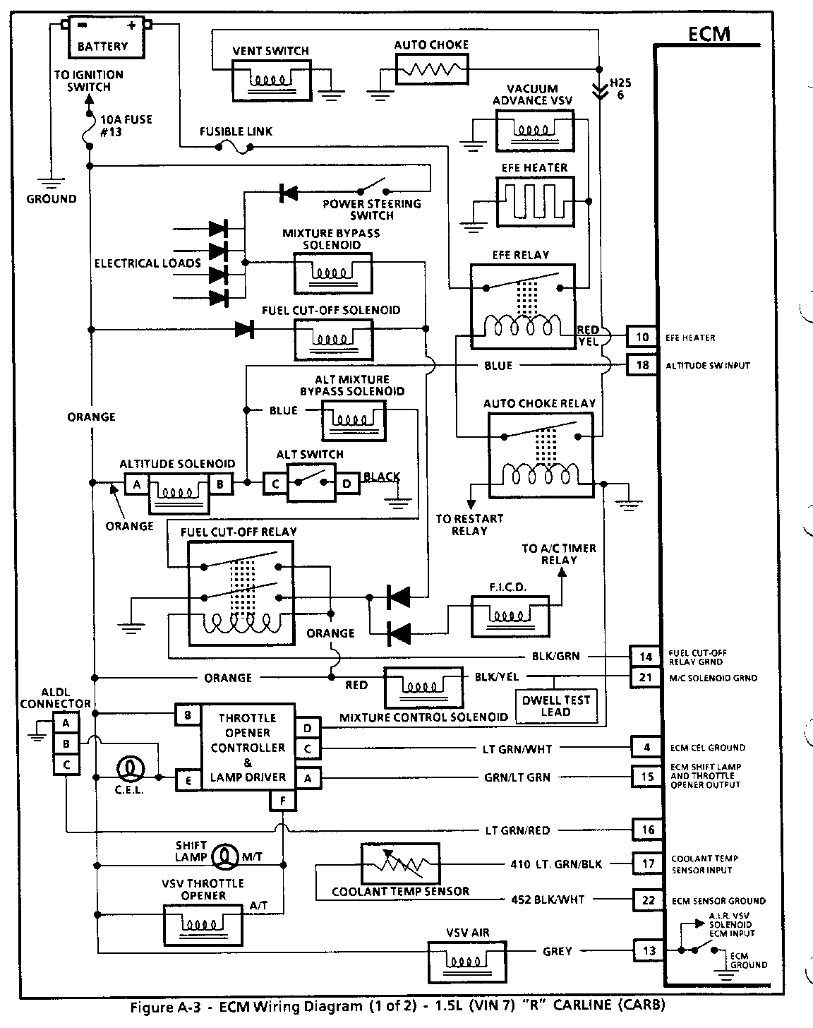
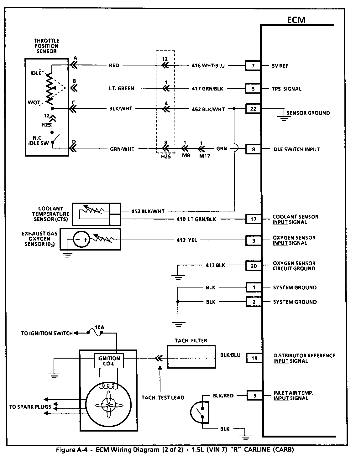
Pages 6E1 - A-4, A-5, A-34, A-52 and Cl-12; additional wire colors indicated.
Pages 6E1-C2-5; the carburetor connector is relabeled and the wire colors are corrected.
Page 6E1-C4-4; chart designation is clarified.
Pages 6E1-C16-3 through C16-7; are corrections made to the fault tree on page C16-5. The diagnostics are adjusted to include a functional check of the altitude solenoid valve.
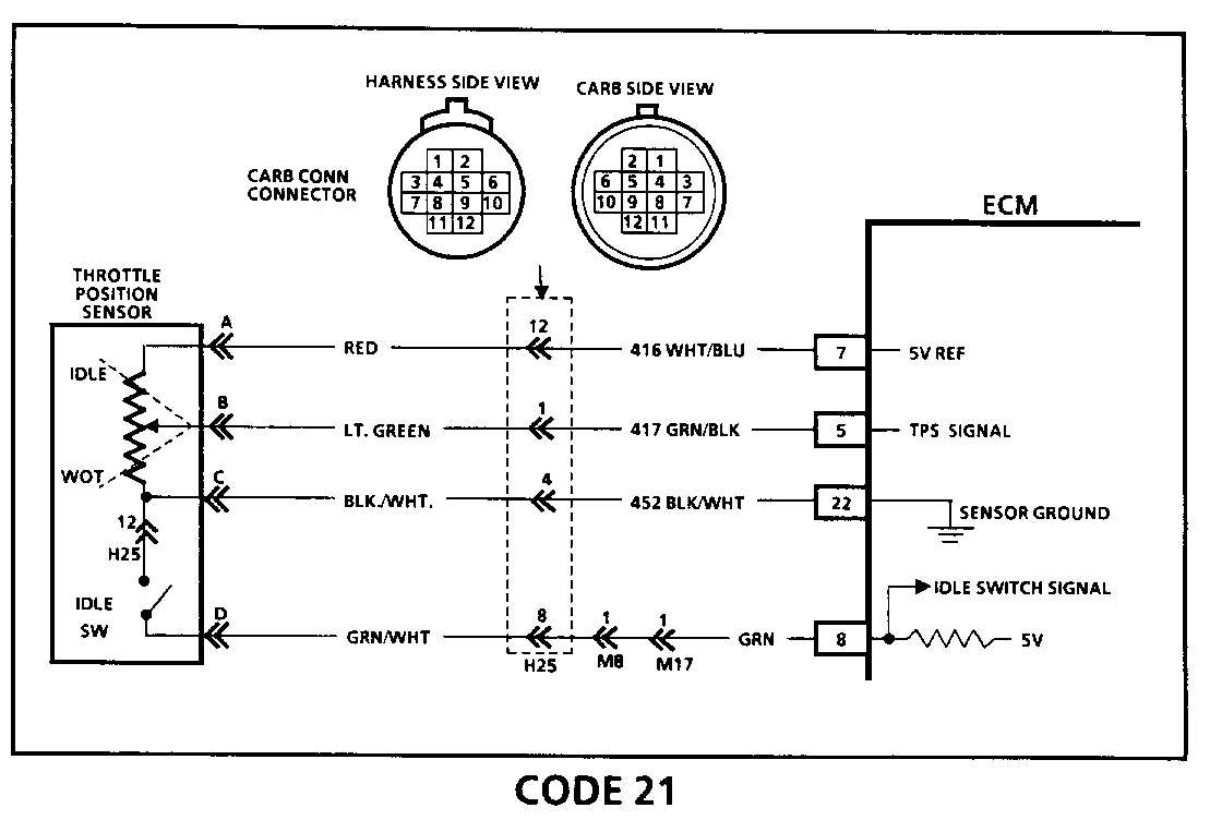
CODE 21 THROTTLE POSITION SENSOR (TPS) AND IDLE SWITCH CIRCUIT 1.5L (VIN 7) "R" CARLINE (CARB)
Circuit Description:
The Throttle Position Sensor (TPS) provides a voltage signal that changes relative to the throttle valve. Signal voltage will varyfrom less than .80 volts at idle to about 4.5 volts at wide open throttle (WOT).
The idle switch provides the ECM with information used to decide closed loop operation and indicates the off-idle condition to the ECM. This switch is normally closed at idle and opens above 1800 RPM, which is then the off-idle condition.
The TPS signal is one of the most important inputs used by the ECM for fuel control and for many of the ECM controlled outputs.
Test Description: Numbers below refer to circled numbers on the diagnostic chart.
1. These tests will determine if the idle switch portion of the circuit is at fault when a code 21 is set.
2. This step checks to see if Code 21 is the result of a hard failure or an intermittent condition. A Code 21 will set if:
- Both WOT and idle are detected for more than one second. OR - TPS is in OFF-IDLE or WOT position. - All of the above conditions present for 32 seconds. - Engine speed is between 500 and 600 rpm.
3. If the ECM recognizes the change of state, the ECM and CKTs 416 and 417 are OK.
4. This step isolates a faulty sensor, ECM, or an open CKT452.
Diagnostic Aids:
A "Scan" tool displays throttle position in volts. Closed throttle voltage should be less than .80 volts. TPS voltage should increase at a steady rate as throttle is moved to WOT.
A Code 21 will result if CKT 452 is open or CKT 417 is shorted to voltage. If Code 21 is intermittent, refer to Section "B".
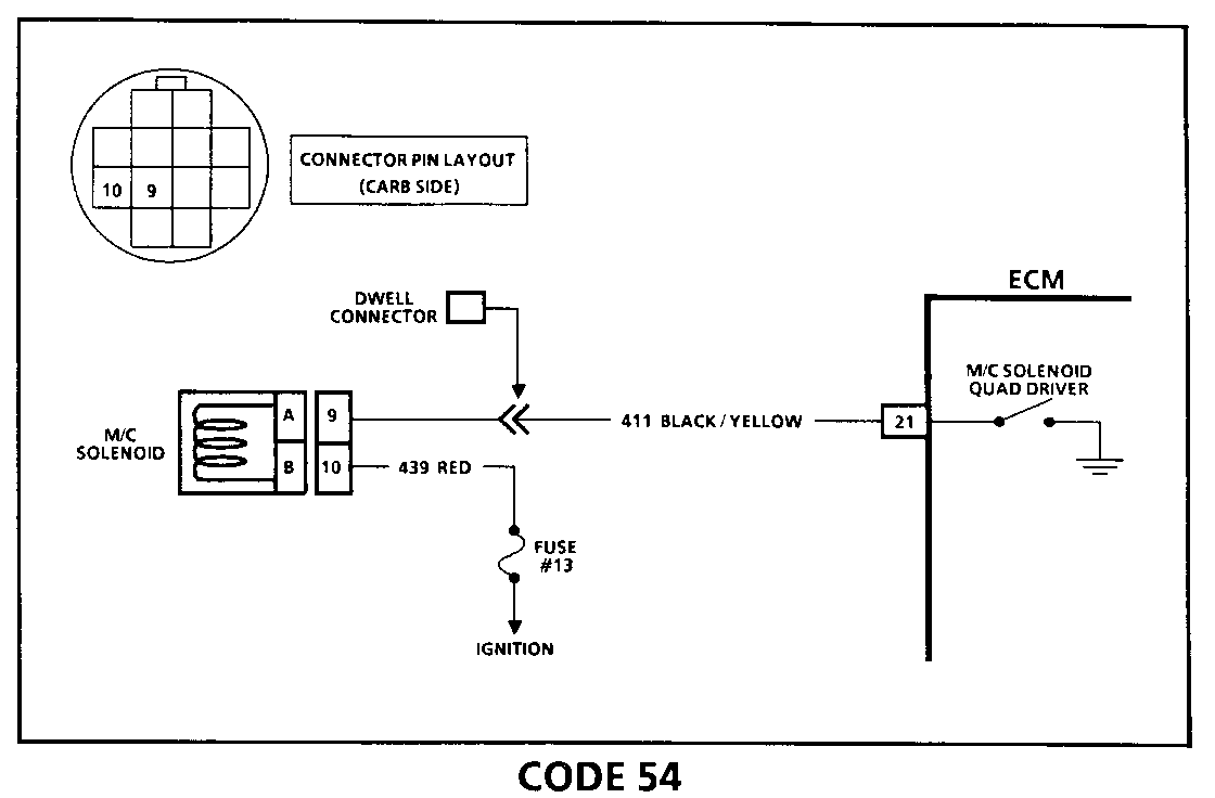
CODE 54 MIXTURE CONTROL (M/C) SOLENOID CIRCUIT (SIGNAL VOLTAGE HIGH) 1.5L (VIN 7) "R" CARLIN E (CARB) Circuit Description:
Code 54 will be set if there is constant high voltage at ECM terminal "21".
A shorted solenoid or shorted CKT 411 to 12V would cause the solenoid to remain in the full rich position, resulting in potential ECM damage, excessive fuel consumption, and excessive exhaust odor.
Test Description: Numbers below refer to circled numbers on the diagnostic chart.
1. Checks the M/C solenoid resistance to determine if the fault is in the solenoid, ECM harness, or ECM. A normal solenoid has about 20 to 32 ohms of resistance. The ECM is equipped with a fault protected quad driver. If the M/C solenoid is under 10 ohms, only the solenoid has to be replaced, not the ECM.
2. Checks to see if reason for high voltage to terminal"21" is a faulty ECM or a short to 12V in CKT 411. If the test light illuminates with both ends of harness disconnected, there is a short to 12V in CKT411.
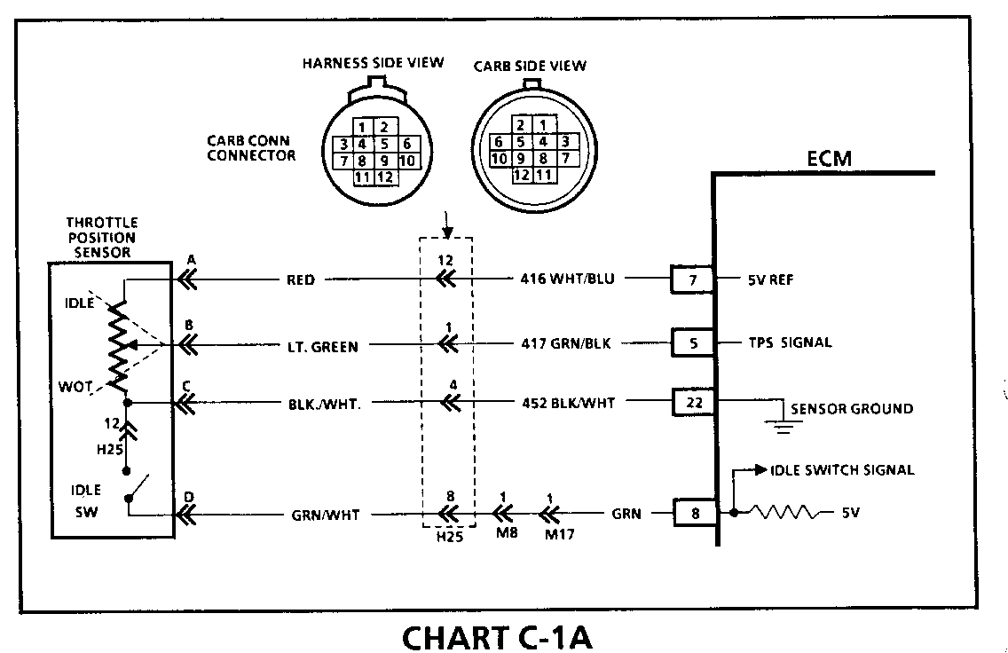
CHART C-1 A THROTTLE POSITION SENSOR (TPS) (ASSEMBLY FUNCTIONAL CH ECK) 1.5L (VIN 7) "R" CARLIN E (CARB) Circuit Description: ------------------- The Throttle Position Sensor (TPS) provides a voltage signal that changes relative to the throttle valve. Signal voltage will vary from less than .80 volts at idle to about 4.5 volts at wide open throttle (WOT).
The idle switch provides the ECM with information used to decide closed loop operation and indicates the off-idle condition to the ECM. This switch is normally closed at idle and opens above 1800 RPM, which is then the off-idle condition.
The TPS signal is one of the most important inputs used by the ECM for fuel control and for many of the ECM controlled outputs.
Diagnostic Aids:
A "Scan" tool displays throttle position in volts. Closed throttle voltage should be less than .80 volts. TPS voltage should increase at a steady rate as throttle is moved to WOT.
CARBURETOR DISASSEMBLY
NOTICE: The idle mixture adjusting screw is plugged, according to the regulations, after adjustment at the factory. However, if adjustment is necessary, removing the plug is possible -- but the screw must be plugged again after adjustment is completed.
Be sure to check that there are no traces of abrasion, damage, fuel leakage, etc., on each part before disassembly of the carburetor.
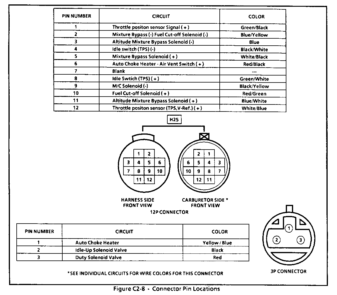
Be sure to remove the wire pins, necessary for disassembly of each component, from the connectors. Figure C2-8 shows pin location and wire color for each connector.
IGNITION TIMING ADJUSTMENT
Adjust
1. Connect the timing light lead to the Number 1 spark plug wire.
2. Loosen the distributor mounting bolt.
3. Using the timing light, algn the notched line on the crankshaft pulley with the mark on the timing cover. While aligning the notched line on the crankshaft pulley with the timing light, adjust the ignition timing by turning the distributor clockwise or counterclockwise as required. See the timing specifications listed in the chart below.
4. After adjustment of the ignition timing, tighten the distributor mounting bolt.
SPARK PLUG WIRES
Inspect
Check the spark plug wires for broken insulation. Check the terminals for corrosion or damage. Replace if necessary.
Measure
Measure spark plug cables for resistance and replace the cables if the resistance deviates from the specified value. Refer to value in chart.
SPARK PLUG WIRE # RESISTANCE VALUES 1 6.44 - 15.03 oh ms 2 5.29 - 12.34 oh ms 3 4.81 - 11.2 ohms 4 3.35 - 7.82 ohms
SPARK PLUGS
Spark plug inspection is an excellent way to determine overall engine performance and efficiency.
If spark plug fouling is excessive, check the fuel and electrical systems for possible causes of trouble. If fuel and electrical systems are normal, install spark plugs of a higher heat range. If burning of the insulator and electrodes is considerable, install spark plugs of a lower heat range.
Inspect
1. Check the electrodes and the insulators for cracks. Replace if faulty.
2. Check the electrodes for wear and replace as necessary.
3. Check the gaskets for damage and replace as necessary.
Measure
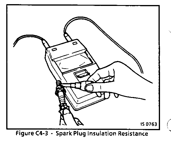
1. Spark plug insulation resistance should be 50 megohms. Refer to Figure C4-3.
2. Spark plug gap should be l.05mm(O.04).
PARTS INFORMATION
PART NAME GROUP --------- ----- DistributorAssembly 2.361 IgnitionCoil 2.170 DistCap 2.367 DistRotor 2.382 SparkPlugs 2.270 SparkPlugWire 2.239 VacuumAdvance 2.410 Pick-upCoil 2.383 IgnitionModule 2.385
DIAGNOSIS
RESULTS OF INCORRECT OPERATION
- Stalling - Rough idle - Black smoke from exhaust
Inspect
- For cracked hoses or restrictions
Remove or Disconnect
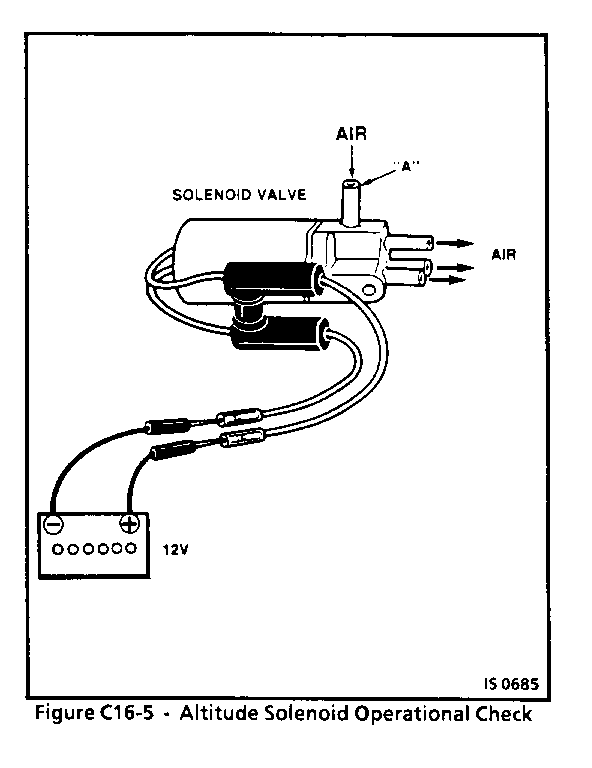
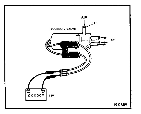
1. All three hoses from the Altitude Solenoid Valve.(Figure C 16-5)
2. Blow into Hose "A" and,
3. Apply 12 volts to the Altitude Solenoid connectors.
4. Check for air flow out of all three hoses (indicating properly opening valve).
5. Remove voltage, valve should close. Replace any valves that do not operate as indicated with proper voltage applied.
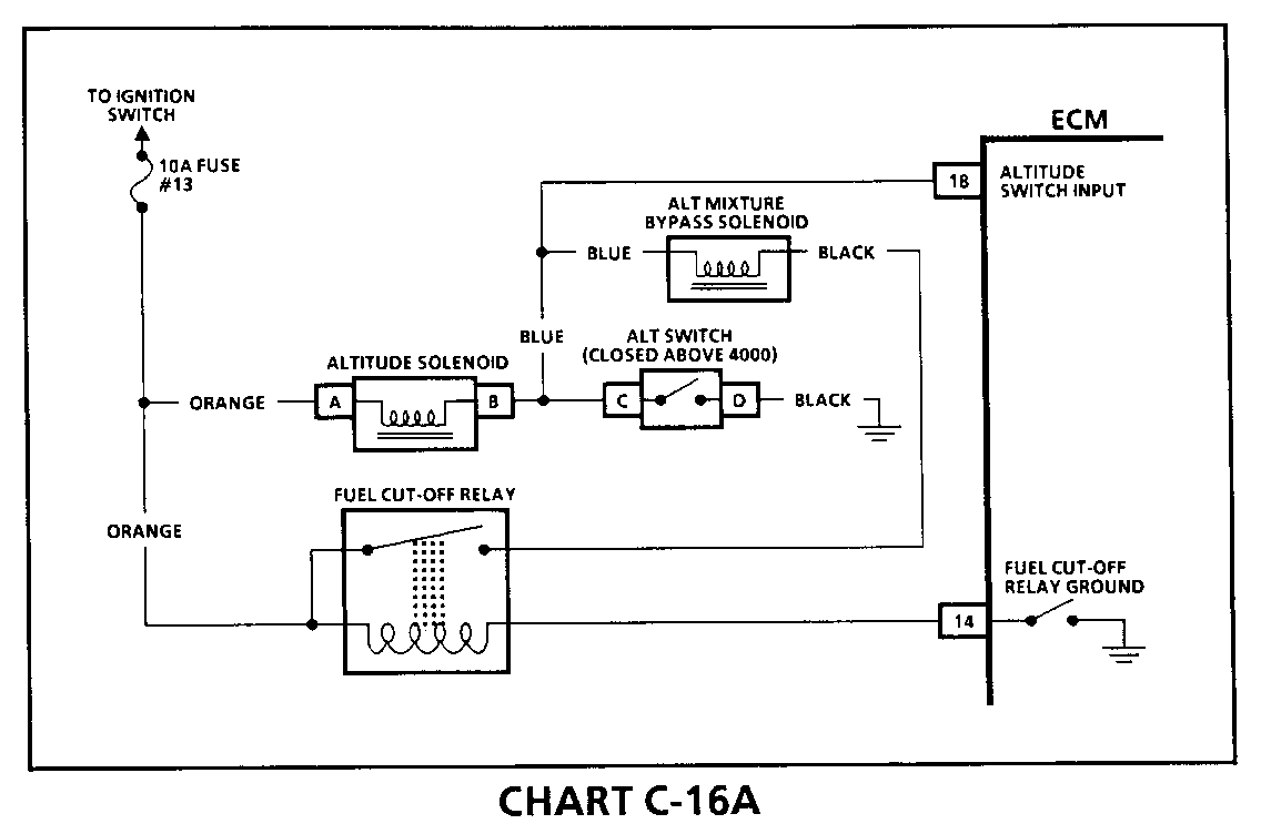
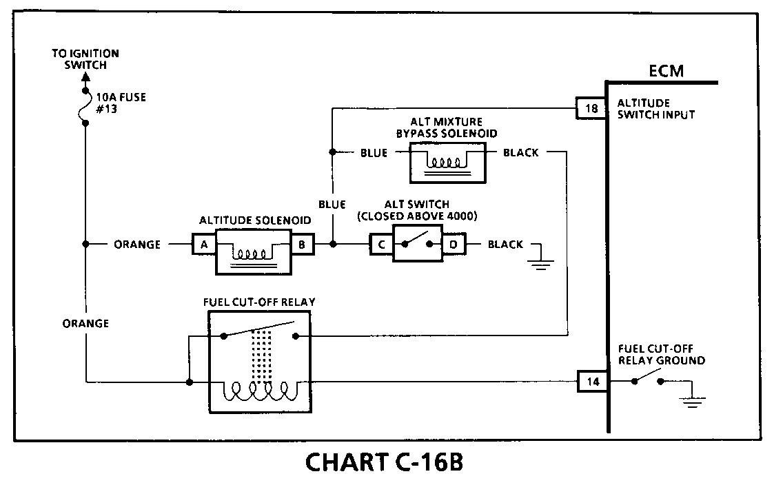
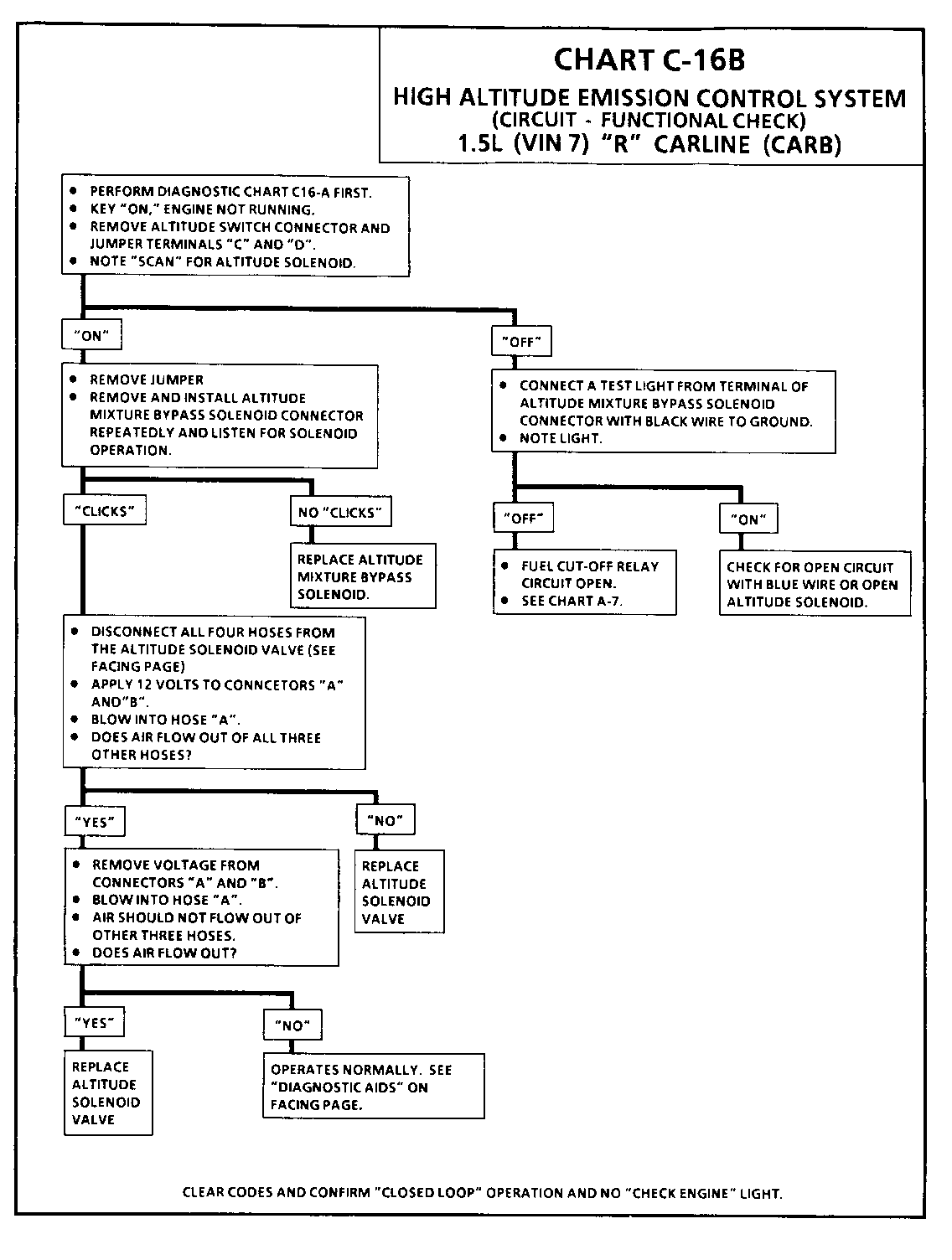
6. See CHART C-16A & 16B on following pages, foradditional diagnosis of High Altitude Emissions Control System problems.
ON-CAR SERVICE
Replace all cracked or deformed hoses. Be sure to use Hose Routing Diagram, Figure A-5, in Section "A".
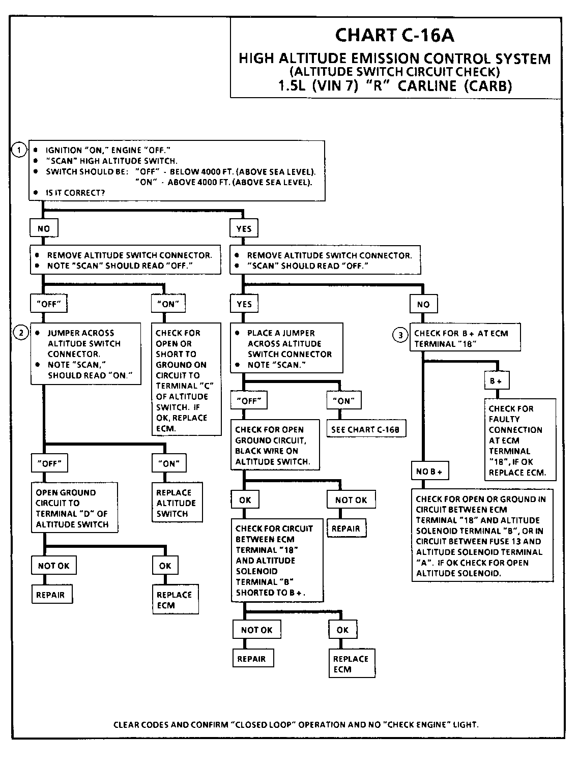
CHART C-16A HIGH ALTITUDE EMISSION CONTROL SYSTEM (ALTITUDE SWITCH CIRCUIT CH ECK) 1.5L (VIN 7) "R" CARLINE (CARB) Circuit Description: ------------------- At high altitudes (above 4000 ft.) the Altitude Sensing Switch will close the circuits between the battery and the Altitude Mixture Bypass Solenoid and the Altitude Solenoid.
The Altitude Solenoid Valve will open the passage between the air cleaner and the carburetor. At this time the Mixture Bypass Solenoid Valve will be activated and will open the port for additional air/fuel mixture to stabilize RPM.
The Altitude Switch is:
Closed at high altitude and, Open at low altitude.
Test Description: Numbers below refer to circled numbers on the diagnostic chart.
1. Determines whether Altitude Switch is functioning normally.
2. Determines if Altitude Switch circuit is open or grounded or if ECM is faulty.
3. Looks for faulty Altitude Solenoid circuit or Altitude Solenoid, or B + on ECM terminal "18".
Diagnostic Aids:
If High Altitude circuit malfunctions at verv high altitude, Code 45 may be stored.
- If engine operation is badly affected, carburetor passages may be plugged. See Section "6C".
CHART C-16B HIGH ALTITUDE EMISSION CONTROL SYSTEM (ALTITUDE SWITCH CIRCUIT CH ECK) 1.5L (VIN 7) "R" CARLINE (CARB) Circuit Description: ------------------- At high altitudes (above 4000 ft.) the Altitude Sensing Switch will close the circuits between the battery and the Altitude Mixture Bypass Solenoid and the Altitude Solenoid.
The Altitude Solenoid Valve will open the passage between the air cleaner and the carburetor. At this time the Mixture Bypass Solenoid Valve will be activated and will open the port for additional air/fuel mixture to stabilize RPM.
The Altitude Switch is:
Closed at high altitude and, Open at low altitude.
Diagnostic Aids:
If High Altitude circuit malfunctions at verv high altitude, Code 45 may be stored.
- If engine operation is badly affected, carburetor passages may be plugged. See Section "6C".
General Motors bulletins are intended for use by professional technicians, not a "do-it-yourselfer". They are written to inform those technicians of conditions that may occur on some vehicles, or to provide information that could assist in the proper service of a vehicle. Properly trained technicians have the equipment, tools, safety instructions and know-how to do a job properly and safely. If a condition is described, do not assume that the bulletin applies to your vehicle, or that your vehicle will have that condition. See a General Motors dealer servicing your brand of General Motors vehicle for information on whether your vehicle may benefit from the information.
