SERVICE MANUAL UPDATE - SEC. 4D DRIVE AXLE REPLACEMENT

SUBJECT: SERVICE MANUAL UPDATE SECTION 4D DRIVE AXLE REPLACEMENT
VEHICLES AFFECTED: 1990-93 GEO STORM
The service procedure contained in this bulletin replaces the "Drive Axle" procedure in DRIVE AXLE (Section 4D) of the 1990-93 GEO Storm Service Manuals (ST371-90, ST371-91, ST371-92 and ST371-93, respectively). Use this procedure whenever removing or installing drive axles on a Geo Storm/Isuzu Impulse.
DRIVE AXLE
Remove or Disconnect
Tools Required: J 21687-02 Tie Rod End Remover J 34754 Inner Drive Joint Seal Protector
NOTICE: Care must be exercised to prevent the differential-side joint from being over-extended. When either end of the shaft is disconnected, over-extension of the differential-side joint could result in separation of internal components and possible joint failure. The J 34754 axle shaft seal protectors should always be used when service is performed on or near the drive axles. Failure to observe this precaution can result in interior joint or seal damage and possible joint failure.
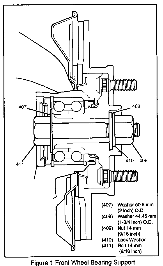
NOTICE: If the vehicle is to be lowered to the ground and moved, the front wheel bearings must be supported with a 14 mm (9/16 inch) bolt, on 44.45 mm (1 3/4 inch washer, on 50.8 mm (2 inch) washer and a 14 mm (9/16 inch) nut assembled through the drive shaft opening in the wheel hub (Figure 1). Tighten the nut and bolt to 54 N.m (40 lb.ft.).
1. Front wheel cover or cap from front wheel
2. Front tire and wheel assembly. Refer to SECTION 3E
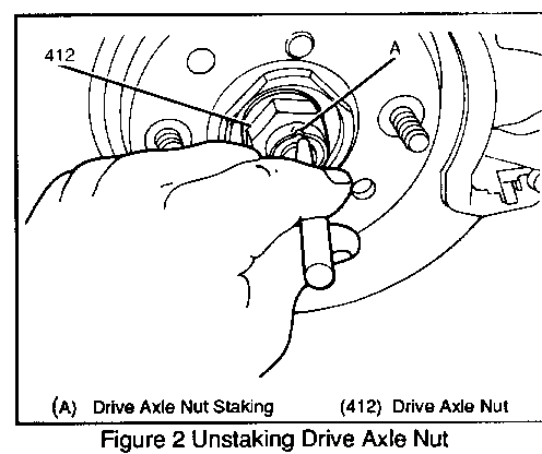
0 Unstake drive axle nut (Figure 2)
3. Drive axle nut from drive axle shaft.
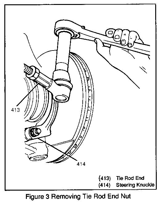
4. One nut from tie rod end (Figure 3)
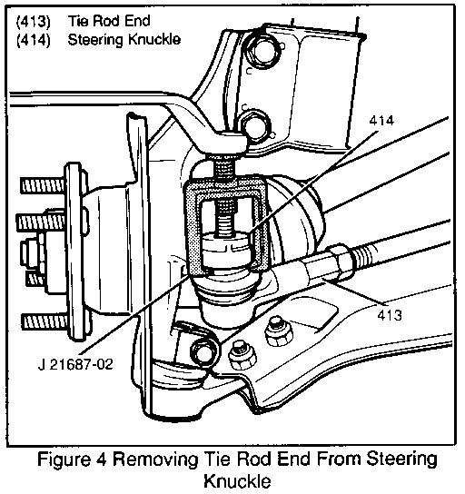
5. Tie rod end from steering knuckle using a J21687-02 (Figure 4)
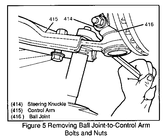
6. Two bolts, tow nuts and separate ball joint and steering knuckle from control arm (Figure 5)
Install the J 34754 protectors to the differential-side and wheel-side joints.
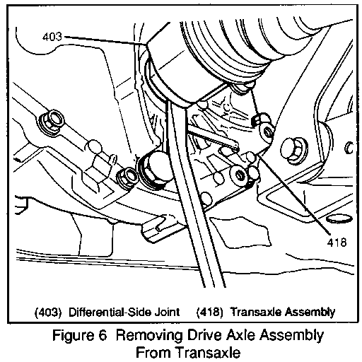
Place a block of wood between a prybar and the transaxle to prevent transaxle damage.
7. Differential-side joint from transaxle by gently prying the differential-side joint housing away and out of the transaxle (Figure 6)
8. Wheel-side joint from steering knuckle and drive axle from vehicle.
Install or connect
1. Wheel-side joint into steering knuckle
2. Differential-side joint into transaxle
3. Remove the J34754 protectors from the differential-side and wheel side joints.
4. Ball joint and steering knuckle to control arm; secure with two bolts and two nuts.
Tighten
Ball joint-to-control arm bolts and nuts to 156 N.m (114 lb.ft)
4. Tie rod end to steering knuckle; secure with one nut.
Tighten
Tie rod end nut to 54 N.m (40 lb.ft)
5. Drive axle nut to drive ale shaft
Tighten
Drive axle nut to 186 N.m (1 37 lb.ft.)
Stake drive axle nut
6. Front tire and wheel assembly. Refer to SECTION 3E.
7. Front wheel cover or cap to wheel
0 Lower vehicle.
Inspect
Toe adjustment; adjust as necessary
Refer to SECTION 3A
General Motors bulletins are intended for use by professional technicians, not a "do-it-yourselfer". They are written to inform those technicians of conditions that may occur on some vehicles, or to provide information that could assist in the proper service of a vehicle. Properly trained technicians have the equipment, tools, safety instructions and know-how to do a job properly and safely. If a condition is described, do not assume that the bulletin applies to your vehicle, or that your vehicle will have that condition. See a General Motors dealer servicing your brand of General Motors vehicle for information on whether your vehicle may benefit from the information.
