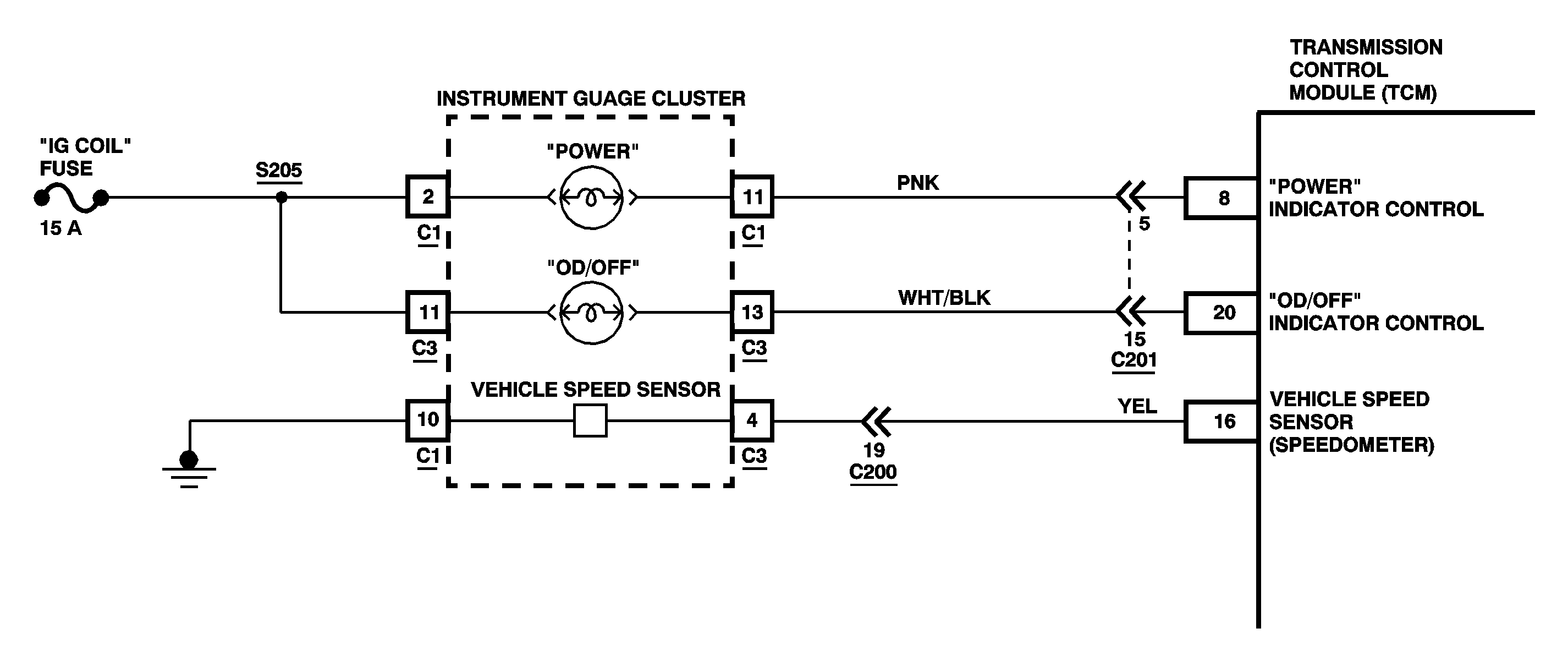
Circuit Description
The Transmission Control Module (TCM) receives an AC voltage input from the Vehicle Speed Sensor (VSS) (Transmission) whenever the drive wheels are rotating. Because the frequency of the AC signal increases with wheel speed, the TCM can calculate vehicle speed from the frequency of the AC signal. The TCM uses this information to determine shift points.
The VSS (Speedometer) serves as a backup to the VSS (Transmission). If the transmission one fails, then the TCM uses the VSS (Speedometer) information to calculate vehicle speed.
DTC Detecting Condition
With 4L switch open, no VSS (Speedometer) signal is received while 10 pulses of the VSS (Transmission) signal are received and this occurred 500 times continuously. Two driving cycle detection logic
Action Taken When the DTC Sets
| • | DTC P1710 is stored. |
| • | The OD/OFF indicator turns on |
| • | The malfunction indicator lamp (MIL) turns on. |
Diagnostic Aids
An intermittent condition may be caused by a poor connection, rubbed wire insulation or a wire broken inside the insulation. Inspect the TCM harness connectors for backed out terminals, improper mating, broken locks, improperly formed or damaged terminals and for poor terminal to wire connections
Test Description
The numbers below refer to the step numbers on the diagnostic table.
-
Checks if DTC P0500 is currently set in the ECM and to proceed with its respective DTC chart first.
-
Checks the operation of the VSS (Speedometer) circuit.
-
Checks for a broken speedometer cable.
-
Checks for a faulty VSS (Speedometer).
Step | Action | Value(s) | Yes | No |
|---|---|---|---|---|
1 | Was the On-Board Diagnostic (OBD) System Check performed? | -- | ||
Is DTC P0500 also currently set? | -- | Go to DTC P0500 Diagnostic in Engine Controls | ||
Does the resistance values change between continuity and infinity a few times as the wheel is rotated? | -- | |||
Does the speedometer cable spin? | -- | |||
5 | Inspect for a broken or disconnected speedometer cable. Repair as necessary. Is the action complete? | -- | -- | |
Using a DVM measure the resistance between VSS (speedometer) output terminals while rotating the speedometer shaft. Does the resistance values change between continuity and infinity 4 times per each speedometer shaft revolution? | -- | |||
7 | Replace the VSS (speedometer). Is the action complete? | -- | -- | |
8 |
Is the resistance less than the value specified? | 2 ohms | ||
9 | Inspect the TCM harness connector and I/P cluster connector C3 for poor terminal contact. Is poor terminal contact evident? | -- | ||
10 | Repair the open or high resistance in the YEL wire between the I/P gauge cluster and the TCM. Is the action complete? | -- | -- | |
11 |
Does the DTC reset? | -- | ||
12 | Repair the terminal or connection that exhibits poor contact and recheck. Is the action complete? | -- | -- | |
13 | Replace the TCM. Is the action complete? | -- | -- | |
14 | Refer to Diagnostic Aids in order to correct a possible intermittent malfunction. Is the procedure complete? | -- | -- | |
15 |
Does the scan tool display any DTCs? | -- | Go to the applicable DTC table | System OK |
