Clutch Pedal Height Adjustment
- Loosen the clutch pedal stop locknut (6).
- Turn the clutch pedal stop bolt counterclockwise to lower the clutch pedal toward the floor, or clockwise to raise the clutch pedal height away from floor. Clutch pedal height should be 5.0 mm (0.2 in) above the brake pedal height.

Tighten
Tighten the clutch pedal stop locknut to 13 N·m (115 lb in)
Removal Procedure
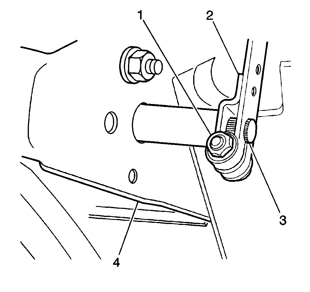
- Remove one nut (1), one bolt (1) and the clutch pedal shaft arm (2) from the clutch pedal shaft (3).
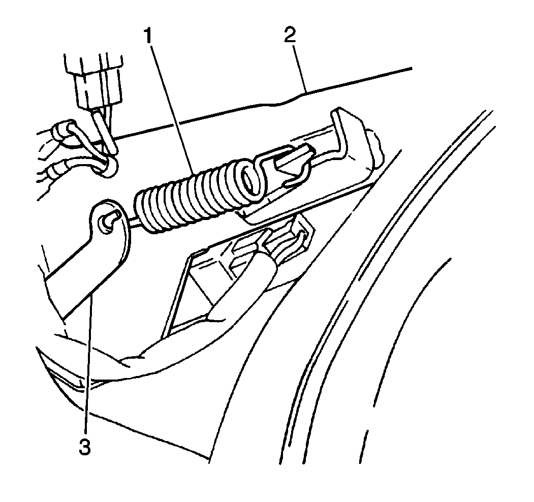
- Remove the clutch pedal return spring (1) from the brake pedal bracket (2).
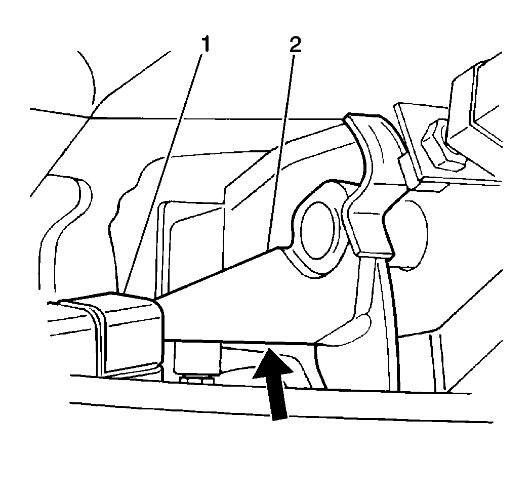
- Push the clutch pedal (2) in to clear the electronic brake control module (EBCM) (1) and slide the clutch pedal (2) to the left (if equipped).
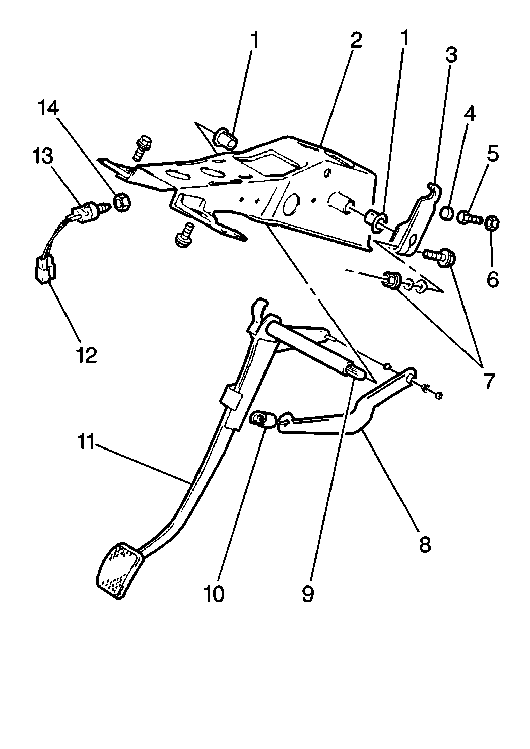
- Remove the clutch pedal (11), clutch pedal return spring lever (8) and the clutch pedal return spring (10) from the brake pedal bracket (12).
- Remove the clutch pedal shaft bushings (1) from the brake pedal bracket (2).
- Inspect the clutch pedal shaft (9) and clutch pedal shaft bushings (1) for excessive wear. Replace as necessary.
- Inspect the clutch pedal lever for distortion or bending. Replace as necessary.
- Inspect the clutch pedal return spring (10) for distortion or weakness. Replace as necessary.

Important: Before removing the clutch pedal shaft arm from the clutch pedal shaft, place a reference mark on the clutch pedal shaft and clutch pedal shaft arm to ensure the correct assembly. If the clutch pedal shaft arm is installed in a position other than the one from which it was removed, the clutch release lever travel will increase or decrease resulting in a misadjusted clutch pedal.


Installation Procedure
- Install the clutch pedal shaft bushings (1) into the brake pedal bracket (2).
- Apply a thin coat of lithium grease to the inside of the clutch pedal shaft bushings (1).
- Install the clutch pedal (11), the clutch pedal return spring lever (8) and the clutch pedal return spring (10) into the brake pedal bracket (2).
- Install the clutch pedal return spring (1) to the brake pedal bracket (2).
- Install the clutch pedal shaft arm (2) onto the clutch pedal shaft aligning index marks made during removal; secure with one bolt (1) and one nut (1).


Notice: Use the correct fastener in the correct location. Replacement fasteners must be the correct part number for that application. Fasteners requiring replacement or fasteners requiring the use of thread locking compound or sealant are identified in the service procedure. Do not use paints, lubricants, or corrosion inhibitors on fasteners or fastener joint surfaces unless specified. These coatings affect fastener torque and joint clamping force and may damage the fastener. Use the correct tightening sequence and specifications when installing fasteners in order to avoid damage to parts and systems.
Important: For clutch adjustment procedures, refer to Clutch Pedal Height Adjustment and Clutch Pedal Free Travel Adjustment .
Tighten
Tighten the clutch pedal shaft arm bolt and nut to 24 N·m (17 lb ft).
