Revised Diagnostic Info for DTC P0400, Exhaust Gas Recirculation System

| Subject: | Revised Diagnostic Information for Diagnostic Trouble Code (DTC) P0400, Exhaust Gas Recirculation System Performance |
| Models: | 1996-1998 Chevrolet Tracker with 1.6 L Engine (VIN 6 -- RPO L01) |
The following diagnostic information should be used for DTC P0400. Please also insert a copy of this information in the appropriate section of the Service Manual.

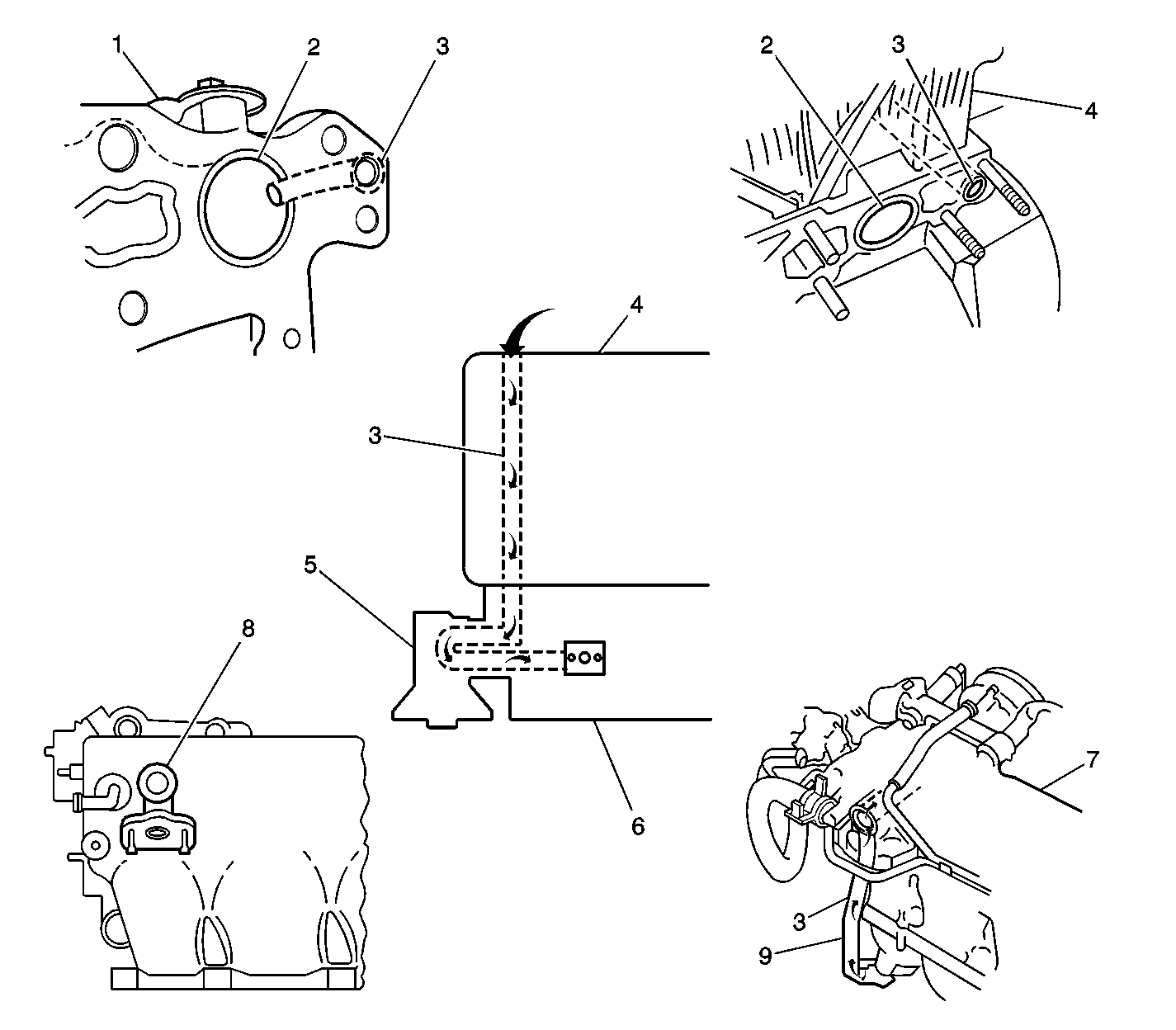
EGR gases are drawn by engine vacuum from the number four cylinder exhaust manifold (1) chamber (2), through the back side of the cylinder head (3), into the intake manifold (6), through the EGR valve (5), back into the intake manifold (6), up the EGR tube (9) to the intake surge tank (plenum) (7) where the EGR gases are merged with the fresh air in the intake air stream.
Following this procedure will ensure the proper diagnosis of the three components of the EGR system (electrical, vacuum and EGR inert gas air flow).
- Perform the Powertrain On-Board Diagnostic (OBD) System Check.
- Is a DTC P0400 displayed?
- Properly block both front and rear wheels. Install the exhaust hose to the tail pipe in the usual manner.
- Firmly set the park brake, place the transmission in PARK (automatic) or Neutral (manual). Start the engine.
- Run the engine until the normal operating temperature of the engine coolant is displayed on the Tech 2 (80-90°C (176-194°F)).
- Observe the engine operation. Is any abnormal condition observed?
- Using the Tech 2 scan tool, turn on the EGR. Does the engine immediately stall?
- With the engine idling, lift up on the EGR valve diaphragm. Did the engine stall?
- If the engine did not stall, the EGR system has a restriction in the EGR flow. The system will be separated into two halves for the balance of the diagnostic procedure.
- Shut off the engine. Remove the EGR tube, which runs from the intake manifold to the intake surge tank (plenum).
- Try to start the vehicle. Will the engine start?
- Remove the necessary components to access the air horn of the throttle body. While holding the throttle plate in the wide open position, look into the throttle body intake opening. At about the 12 o'clock position, you should find a 10 mm (13/32 in) diameter opening. Insert a #3 Phillips screwdriver (the blade of the screwdriver should extend about 250 mm (10 in) from the handle and the blade should be well greased to catch the contaminants) into the throttle bore and gently clean the passageway in the plenum. This opening is only about an inch in depth. You should see debris falling out the opening where the EGR tube was attached.
- Complete the cleaning process by cleaning the EGR passage and the back side of the throttle plate with carburetor cleaner in the normal manner.
- Tape over the EGR tube to the plenum opening with masking tape.
- Start the engine. With the engine idling (and with the aid of gloves or a cloth rag), squeeze the diaphragm of the EGR valve to open the valve. Listen carefully. You should be able to hear a change in pitch. The change in pitch should sound like what you hear when the tube is missing from an AIR pump, but slightly lower in volume. If this sound is not heard, inspect for a restriction of the EGR passages from the EGR valve back to the #4 exhaust manifold chamber.
- Remove the tape installed in Step 14. The engine should stall immediately. If the engine does not stall, the EGR tube in the plenum is still restricted. Clean it again.
- Replace all the necessary gaskets and reassemble the engine completely.
- Using the Tech 2, clear all the DTCs.
- Road test the vehicle with the Tech 2 installed under the conditions necessary to run the diagnostic test for P0400 until the test either passes or fails and resets the trouble code.
- If the DTC P0400 resets, the problem is either with the vacuum system portion or the electrical portion of the EGR system. Refer to DTC P0400 in the Service Manual for the proper diagnostic steps.
If No, exit this procedure and Service Manual DTC P0400 diagnosis.
If Yes, continue with this diagnostic procedure.
If Yes, diagnose and repair before proceeding with the balance of the diagnostic procedure.
If No, continue with this procedure.
If Yes, the EGR system is acting as it was designed. Clear the code and road test the vehicle within the Freeze Frame conditions required to run the diagnostics.
If No, proceed to the next step.
Caution: The EGR valve is hot. Wear gloves in order to prevent personal injury.
If Yes, the problem is determined to be an electrical or vacuum supply problem. Use previously published procedures found in the Engine Controls subsection of the 1998 Tracker Service Manual for DTC P0400, starting with Step 4.
If No, continue with the next step.
Important: Refer to Figure 1 for reference.
To remove this tube without damage, remove the two retainers from the lower intake manifold and place them on the upper attaching bolts, double nutting the studs. Remove the studs by placing a wrench on the top nut. Remove the tube.
If Yes, the restriction is in the intake plenum. Proceed to the next step.
If No, the restriction is somewhere down stream from the intake manifold to EGR tube interface.
