SERVICE MANUAL UPDATE SEC. 7A A/T SELECT/KICKDOWN CABLE ADJ.

SUBJECT: UPDATE SECTION 7A AUTOMATIC TRANSMISSION SELECT CABLE AND KICK DOWN CABLE ADJUSTMENT (ADD'L PROCEDURE)
VEHICLES AFFECTED: 1989-91 TRACKER
This bulletin adds adjustment procedures to the "SELECT CABLE" installation procedure and the "KICK DOWN CABLE" installation procedures found on page 7A-4 of the 1989 Tracker Service Manual (ST377-89, page 7A-7 of the 1990 Tracker Service Manual (ST377-90) and page 7A-8 of the 1991 Tracker Service Manual (ST377-91).
Refer to this Bulletin whenever "Select of Kick Down Cable" adjustment is necessary.
AUTOMATIC TRANSMISSION GEAR SHIFT SELECT CABLE ADJUSTMENT
1. Raise and suitably support vehicle enough to gain access to its underside, while still maintaining access to the passenger compartment. Refer to General Information (Section OA) in the 1989, 1990 or 1991 Tracker Service Manual.
2. With the select cable installed at the transmission and at the gear shift lever, and with the centre console cover removed, place the gear shift select lever into the "N" (neutral) position.
3. Look at the gear shift lever assembly from the right side of the vehicle. With the shift lever in the "N" (neutral) position, two holes will line up at the rear of the lever detent bracket (below the level of the console cover). Insert a pin in through this hole to hold the lever in the "N" (neutral) position.
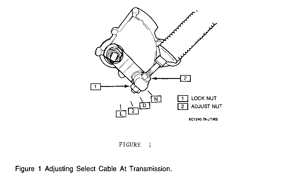
Figure 1 - Adjusting Select Cable at Transmission
4. At the transmission, place the manual select lever in the neutral position. Tighten the lock and adjusting nuts to hold this position, as shown in Figure 1.
Tighten
* Cable lock nut to 7 N.m (62 in.lbs.).
5. Remove the pin inserted earlier from the gear shift lever assembly.
6. Move shift lever to the "L" (low) position to verify that the transmission manual shift lever was actually in the neutral position when the cable lock and adjustment nuts were tightened. If the select cable adjustment was made incorrectly, the lever will not shift into the "L" (low) position.
7. Move shift lever into "P" (park) to further verify shift lever operation.
8. Install centre console trim (two screws at front, retaining clips at rear).
9. Lower the vehicle.
AUTOMATIC TRANSMISSION KICK DOWN CABLE ADJUSTMENT
1. Make sure that the accelerator cable is properly adjusted. Refer to Engine Fuel (Section 6C) in the 1989, 1990 or 1991 Tracker Service Manual.
2. Loosen kick down cable lock and adjusting nuts.
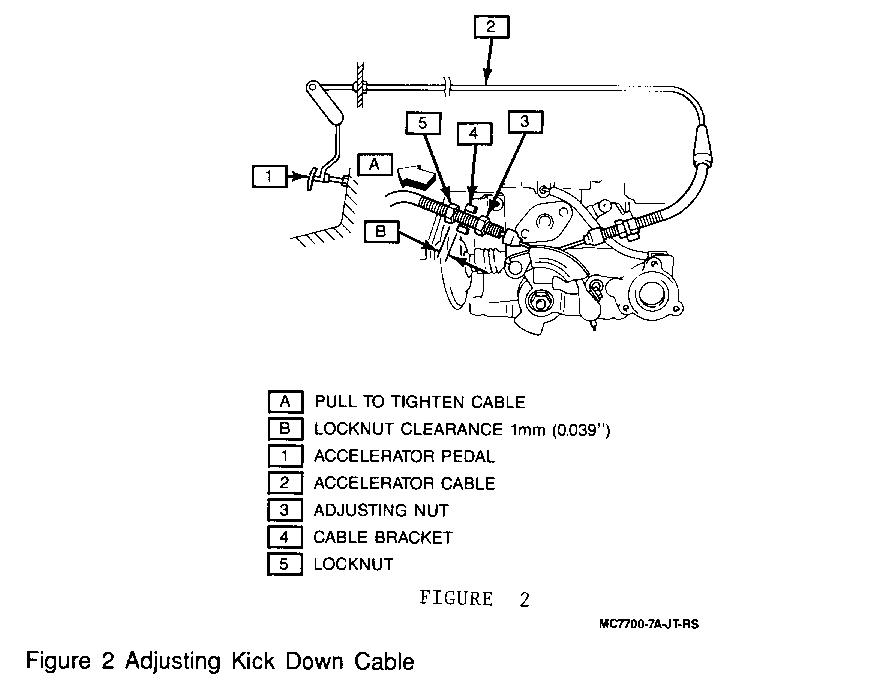
Figure 2 - Adjusting Kick Down Cable
3. With a second technician fully depressing the accelerator pedal, pull the kick down cable tight, in direction A, as shown in Fig. 2.
4. Turn the lock nut to within 1 mm (0.039") of the cable bracket while the cable is being pulled tight.
important: Make sure the adjusting nut is not in contact with the bracket and this point.
5. Have the second technician release the accelerator pedal and keeping the lock nut-to-bracket clearance at 1 mm (0.039"), turn the adjusting nut until it engages the bracket, fitting inside it.
6. When the adjusting nut is positioned flush within the cable bracket, tighten lock nut fully, reducing lock nut-to-bracket clearance to 0 mm (0.0").


General Motors bulletins are intended for use by professional technicians, not a "do-it-yourselfer". They are written to inform those technicians of conditions that may occur on some vehicles, or to provide information that could assist in the proper service of a vehicle. Properly trained technicians have the equipment, tools, safety instructions and know-how to do a job properly and safely. If a condition is described, do not assume that the bulletin applies to your vehicle, or that your vehicle will have that condition. See a General Motors dealer servicing your brand of General Motors vehicle for information on whether your vehicle may benefit from the information.
