SERVICE MANUAL UPDATE SEC. 7D TRANSFER CASE UNIT REPAIR

Subject: TRANSFER CASE UNIT REPAIR
Model and Year: 1991 GEO TRACKER
Just prior to 1991 model year start of production, a friction gear and friction gear retainer were added to the two-wheel and four-wheel drive Tracker manual transmissions. This bulletin amends information found in Transfer Case (Section 7D) of the 1991 GEO Tracker Service Manual (ST377-91).
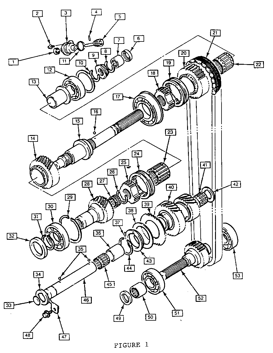
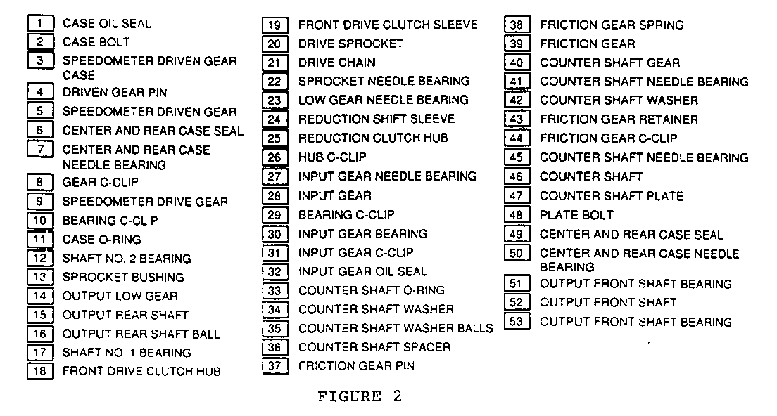
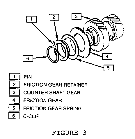
Figures 2 and 3 of this bulletin replace Figure 2 found on page 7D-3. In addition, the Transfer Case Unit Repair disassembly and assembly procedures have been corrected.
DISASSEMBLY
After the counter shaft gear has been removed from the counter shaft (Step 15 - page 7D-6), the following procedure must be performed:
Remove the friction gear C-clip, friction gear retainer, friction gear spring, friction gear and pin from the counter shaft.
ASSEMBLY
After the drive shaft has been installed into the center case (Step 26 page 7D-10), the following procedure must be performed:
Install the pin, friction gear, friction gear spring, friction gear retainer and the C-dip to the counter shaft (Figure 1).
[1] CASE OIL SEAL [19] FRONT DRIVE CLUTCH SLEEVE [2] CASE BOLT [20] DRIVE SPROCKET [3] SPEEDOMETER DRIVEN GEAR [21] DRIVE CHAIN CASE [22] SPROCKET NEEDLE BEARING [4] DRIVEN GEAR PIN [5] SPEEDOMETER DRIVEN GEAR [23] LOW GEAR NEEDLE BEARING [6] CENTER AND REAR CASE SEAL [24] REDUCTION SHIFT SLEEVE [7] CENTER AND REAR CASE [25] REDUCTION CLUTCH HUB NEEDLE BEARING [26] HUB C-CLIP [8] GEAR C-CLIP [27] INPUT GEAR NEEDLE BEARING [9] SPEEDOMETER DRIVE GEAR [28] INPUT GEAR [10] BEARING C-CLIP [29] BEARING C-CLIP [11] CASE O-RING [30] INPUT GEAR BEARING [12] SHAFT NO. 2 BEARING [31] INPUT GEAR C-CLIP [32] INPUT GEAR OIL SEAL [13] SPROCKET BUSHING [33] COUNTER SHAFT O-RING [14] OUTPUT LOW GEAR [34] COUNTER SHAFT WASHER [15] OUTPUT REAR SHAFT [35] COUNTER SHAFT WASHER BALLS [16] OUTPUT REAR SHAFT BALL [36] COUNTER SHAFT SPACER [17] SHAFT NO. 1 BEARING [18] FRONT DRIVE CLUTCH HUB [37] FRICTION GEAR PIN
[38] FRICTION GEAR SPRING [39] FRICTION GEAR [40] COUNTER SHAFT GEAR [41] COUNTER SHAFT NEEDLE BEARING
[42] COUNTER SHAFT WASHER [43] FRICTION GEAR RETAINER [44] FRICTION GEAR C-CLIP [45] COUNTER SHAFT NEEDLE BEARING [46] COUNTER SHAFT [47] COUNTER SHAFT PLATE [48] PLATE BOLT [49] CENTER AND REAR CASE SEAL [50] CENTER AND REAR CASE NEEDLE BEARING [51] OUTPUT FRONT SHAFT BEARING [52] OUTPUT FRONT SHAFT [53] OUTPUT FRONT SHAFT BEARING


General Motors bulletins are intended for use by professional technicians, not a "do-it-yourselfer". They are written to inform those technicians of conditions that may occur on some vehicles, or to provide information that could assist in the proper service of a vehicle. Properly trained technicians have the equipment, tools, safety instructions and know-how to do a job properly and safely. If a condition is described, do not assume that the bulletin applies to your vehicle, or that your vehicle will have that condition. See a General Motors dealer servicing your brand of General Motors vehicle for information on whether your vehicle may benefit from the information.
