SERVICE MANUAL UPDATE-SEC. 1A HEATER CORE REMOVAL & INSTALL

SUBJECT: SERVICE MANUAL UPDATE SECTION 1 A HEATER CORE REMOVAL AND INSTALLATION
VEHICLES AFFECTED: 1989-91 GEO TRACKERS
This bulletin supersedes the heater core removal and installation procedure found in SECTION IA of the following service publications:
1989 Geo Tracker Service Manual (ST377-89) 1990 Geo Tracker Service Manual (ST377-90) 1991 Geo Tracker Service Manual (ST377-91)
Refer to this bulletin when heater core removal and installation becomes necessary.
HEATER CORE:
Remove or Disconnect
Tool Required: J 1859-03 Steering Wheel Puller
1. Negative (-) battery cable from negative (-) battery terminal.
* Place a drain pan or suitable container under radiator.
* Drain engine cooling system. Refer to SECTION 6B of the Geo Tracker Service Manual.
2. Steering wheel horn pad from steering wheel
3. Steering wheel retaining nut from steering wheel.
4. Steering wheel from steering column using a J 1859-03
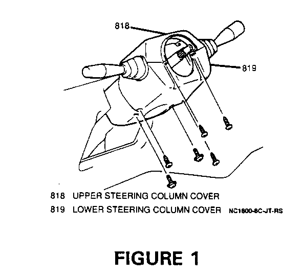
5. Six screws, upper and lower steering column covers from steering column (Figure 1)
6. Lower steering column access cover from instrument panel.
7. Two combination switch electrical connectors from combination switch.
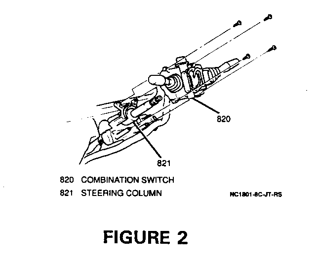
8. Four screws, harness retainer and combination switch from steering column (Figure 2)
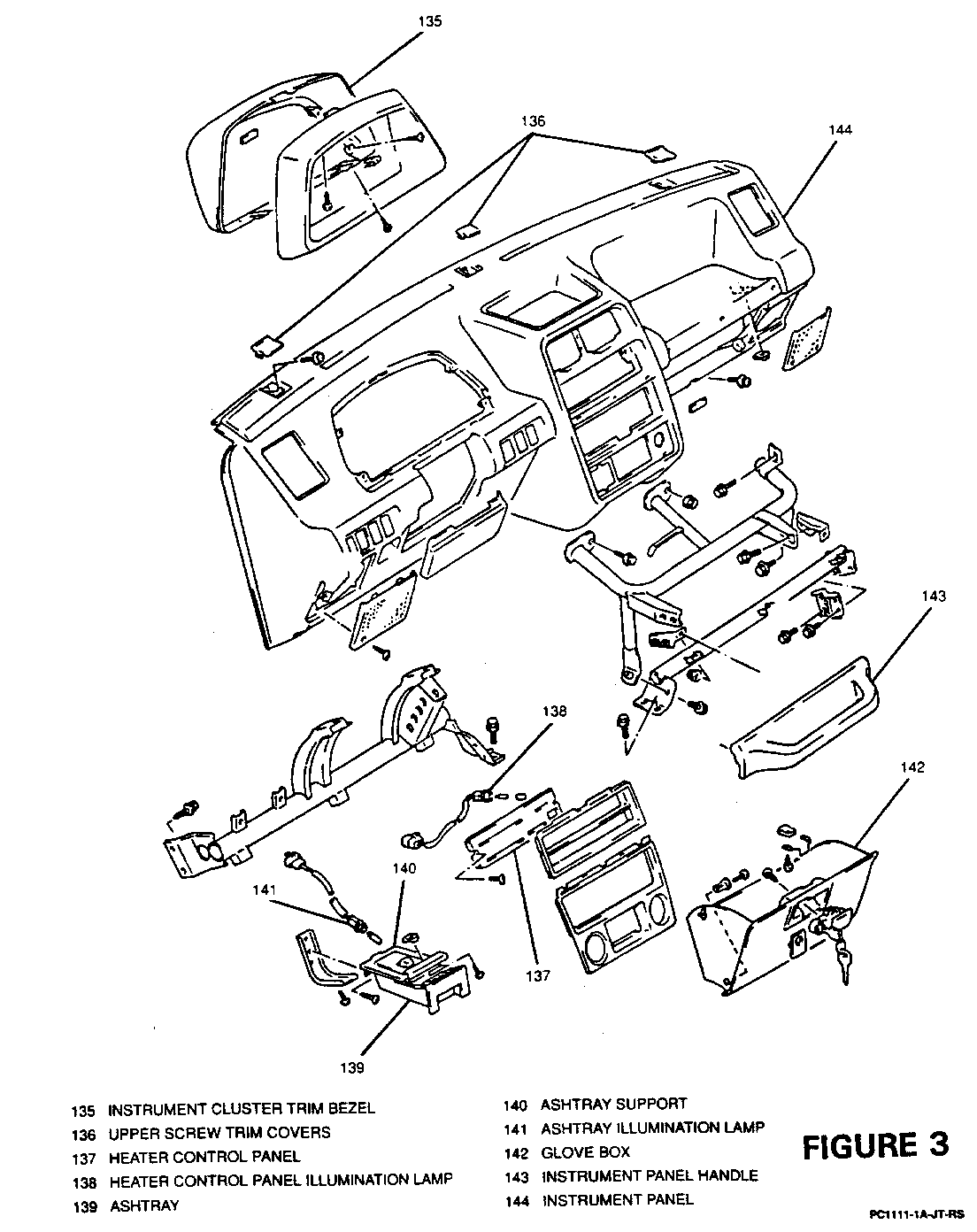
9. Four screws and instrument cluster trim bezel from instrument cluster (Figure 3)
10. Four screws and instrument cluster from instrument panel.
11. Speedometer cable from rear of instrument cluster
12. Instrument cluster electrical connectors from rear of instrument cluster.
13. Four instrument panel wiring harness electrical connectors from engine wiring harness electrical connectors at bulkhead.
14. Three upper screw trim covers and three upper screws from instrument panel (Figure 3)
15. Six screws from lower instrument panel.
16. Heater control knobs and trim bezel from heater control.
17. Two screws from heater control panel (Figure 3)
18. Heater control illumination lamp from heater control panel and heater control panel from heater control (Figure 3)
19. Two screws and heater control from instrument panel
20. Blower switch and A/C switch (if equipped) electrical connectors.
21. Ashtray from instrument panel (Figure 3)
22. Two screws, ashtray illumination lamp from ashtray support and ashtray support from instrument panel (Figure 3)
23. Two screws, glove box push pins and glove box from instrument panel (Figure 3)
24. Two bolts and instrument panel handle from instrument panel (Figure 3)
25. Two screws and hood release cable from instrument panel
26. One bolt from lower center instrument panel support
27. One bolt and ground wire from lower center instrument panel support
28. One bolt, antenna lead and electrical connector from radio and radio from vehicle
29. Instrument panel from bulkhead
30. Heater control cables from heater control
31. Four screws and instrument panel renter support from bulkhead
32. Defroster duct and speedometer cable from heater case
33. Blower motor electrical connector and blower motor from heater case
* Loosed evaporator case bolts and nut from bulkhead (if equipped)
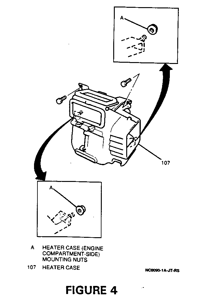
34. Two nuts from heater case on engine compartment side of bulkhead (Figure 4)
35. Two hose clamps and tow heater hoses from heater core on engine compartment side of bulkhead
36. Heater core grommet from heater core on engine compartment side of bulkhead
37. Floor duct from heater case
38. Tow bolts and heater case from bulkhead (Figure 4)
39. One clamp from evaporator case/duct and heater case from passenger compartment
40. One bolt and pipe retaining bracket from heater case
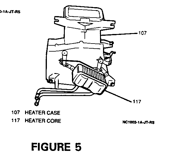
41. One bolt and heater core from heater case (Figure 5)
Install or Connect
1. Heater core into heater case; secure with one bolt
Tighten
* Heater core bolt to 10 N.m (89 lb.in.)
2. Pipe retaining bracket to heater case; secure with one bolt
Tighten
* Pipe retaining bracket bolt to 10 N.m (89 lb.in)
3. Heater case into vehicle; securing evaporator case/duct to heater case with one clamp
4. Heater case to bulkhead; secure with two bolts
Tighten
* Heater case bolts to 15 N.m (11 lb.ft.)
5. Floor duct to heater case
6. Heater core grommet onto heater core on engine compartment side of bulkhead
7. Tow heater hoses to heater core on engine compartment side of bulkhead; secure with tow hose clamps
* Secure heater case on engine compartment side of bulkhead with two nuts.
Tighten
* Heater case nuts to 15 N.m (11 lb.ft.)
* Evaporator case bolts and nuts to 15 N.m (11 lb.ft.) (if equipped)
8. Blower motor electrical connector and blower motor to heater case
9. Defroster duct and speedometer cable to heater case
10. Instrument panel center support to bulkhead; secure with four screws
11. Heater control cables to heater control
12. Instrument panel to bulkhead
13. Antenna lead and electrical connector to radio and radio to instrument panel; secure with one bolt
Tighten
* Radio mounting bolt to 15 N.m (11 Lb.Ft.)
14. Ground wire to lower center instrument panel support; secure with one bolt
Tighten
* Ground wire bolt to 10 N.m (89 lb in)
15. One bolt into lower center instrument panel support
Tighten
*Instrument panel support bolt to 10 N.m (89 lb.in.)
16. Hood release cable to instrument panel; secure with two screws.
17. Instrument panel handle to instrument panel; secure with two bolts
Tighten
* Instrument panel handle bolts to 20 N.m (15 lb.ft)
18. Glove box into instrument panel; secure with two push pins and two screws
19. Ashtray illumination lamp into ashtray support and ashtray support into instrument panel; secure with two screws
20. Ashtray into instrument panel
21. Blower switch and A/C switch (if equipped) electrical connectors
22. Heater control to instrument panel; secure with two screws.
23. Heater control illumination lamp to heater control panel
24. Heater control panel to heater control; secure with two screws
25. Heater control trim bezel and knobs to heater control
26. Lower instrument panel to supports; secure with six screws
27. Upper instrument panel to supports; secure with three screws and insert three trim covers
28. Four instrument panel wiring harness electrical connectors at bulkhead
29. Instrument cluster electrical connectors into rear of instrument luster
30. Speedometer cable to rear of instrument cluster
31. Instrument cluster into instrument panel secure with four screws
32. Instrument cluster trim bezel to instrument cluster; secure with four screws
33. Combination switch to steering column; secure with four screws and harness retainer
34. Two combination switch electrical connectors to combination switch
35. Lower steering column access cover into instrument panel
36. Upper and lower steering column covers onto steering column; secure with six screws.
37. Steering wheel onto steering column; secure with retaining nut
Tighten
* Steering wheel retaining nut to 33 N.m (24 lb.ft)
38. Steering wheel horn pad onto steering wheel
* Refill engine cooling system as necessary. Refer to SECTION 6B of the GEO Tracker Service Manual
* Remover drain pan from under radiator
39. Negative (-) battery cable to negative (-) battery terminal
Tighten
* Negative (-) battery cable-to-negative (-) battery terminal retainer to 15 N.m (11 lb.ft.)
General Motors bulletins are intended for use by professional technicians, not a "do-it-yourselfer". They are written to inform those technicians of conditions that may occur on some vehicles, or to provide information that could assist in the proper service of a vehicle. Properly trained technicians have the equipment, tools, safety instructions and know-how to do a job properly and safely. If a condition is described, do not assume that the bulletin applies to your vehicle, or that your vehicle will have that condition. See a General Motors dealer servicing your brand of General Motors vehicle for information on whether your vehicle may benefit from the information.
