SERVICE MANUAL UPDATE-SEC.1D A/C COMPRESSOR OVERHAUL

SUBJECT: SECTION 1D - A/C COMPRESSOR OVERHAUL
VEHICLES AFFECTED: 1991-92 "M" MODEL AND "E/J" TRUCK
APPLICATION:
----------- Mid-Year 1991-92 M-Car and E/J Trucks.
This bulletin replaces the "A/C Compressor Overhaul" procedures located in Section 1 D of the 1991 and 1992 Metro (Sprint/Firefly) and Tracker Service Manual (ST370-91/92 and ST377-91/92).
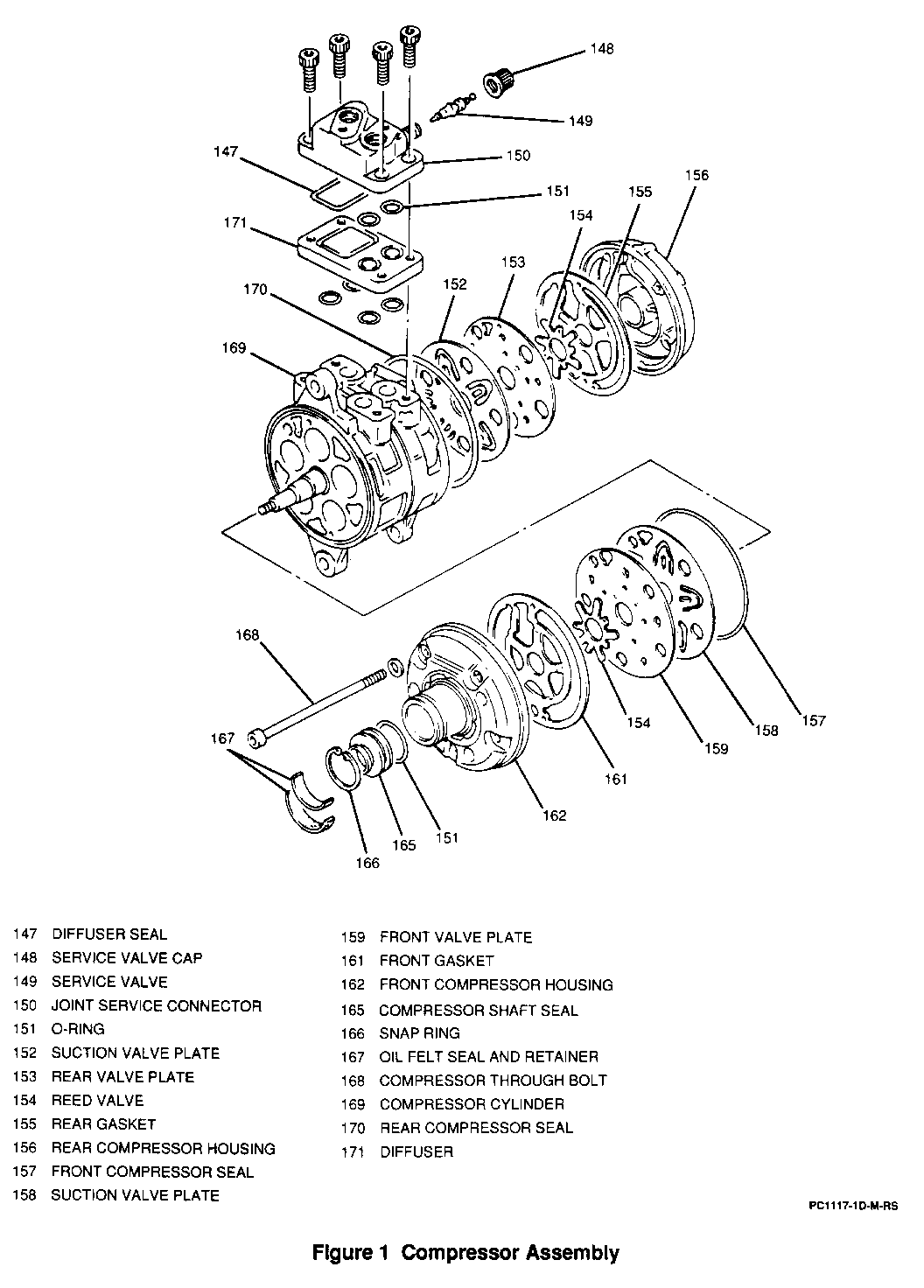
COMPRESSOR ASSEMBLY SERVICE: (FIGURES 1 THROUGH 24) --------------------------------------------------- Remove or Disconnect:
Tool Required: J 33942-8 Seal Seat Remover
1. A/C compressor clutch. Refer to "A/C Compressor Clutch" earlier in this section.
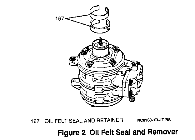
2. Oil felt seal and retainer from shaft. Pry off with screwdriver.
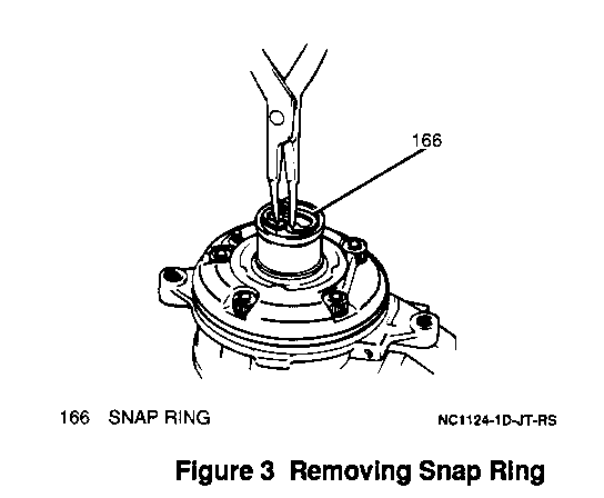
3. Snap ring; using appropriate snap ring pliers . * Apply compressor oil to inner bore to ease disassembly.
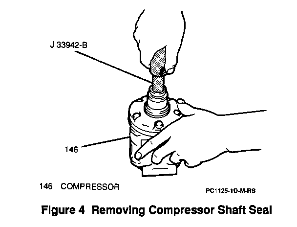
4. Compressor shaft seal using a J 33942-B. Insert tool, turn 45 degrees and pull shaft seal out.
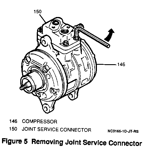
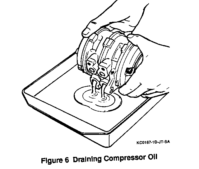
5. Four Allen-head bolts, joint service connector and 0-rings.
o Drain compressor oil into a container and save.
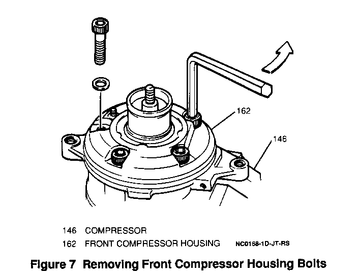
6. Five Allen-head bolts and washers securing front compressor housing.
IMPORTANT: --------- o Do not reuse five front housing washers.
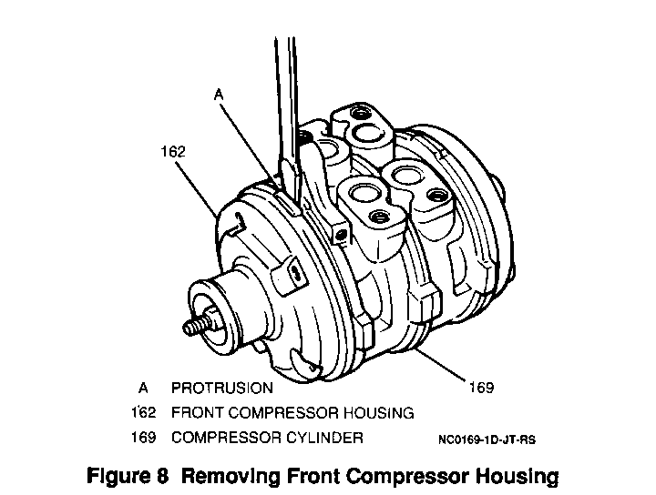
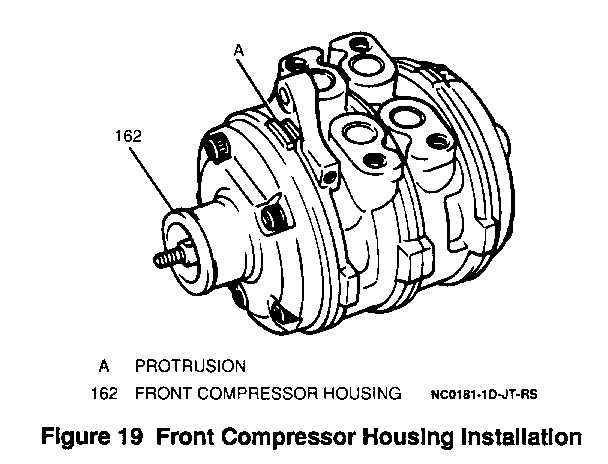
7. Front compressor housing; pry off with a screwdriver.
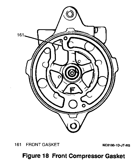
8. Front gasket and reed valve from front of compressor.
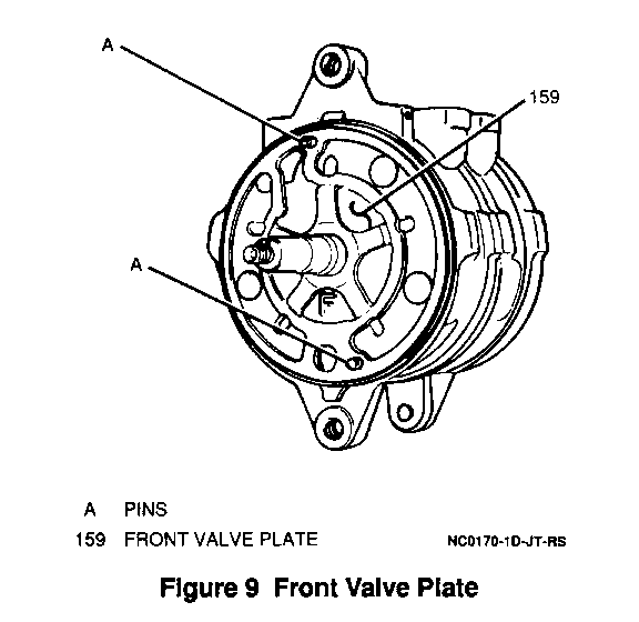
9. Two pins from front of compressor and valve plate .
10. Front suction valve from compressor.
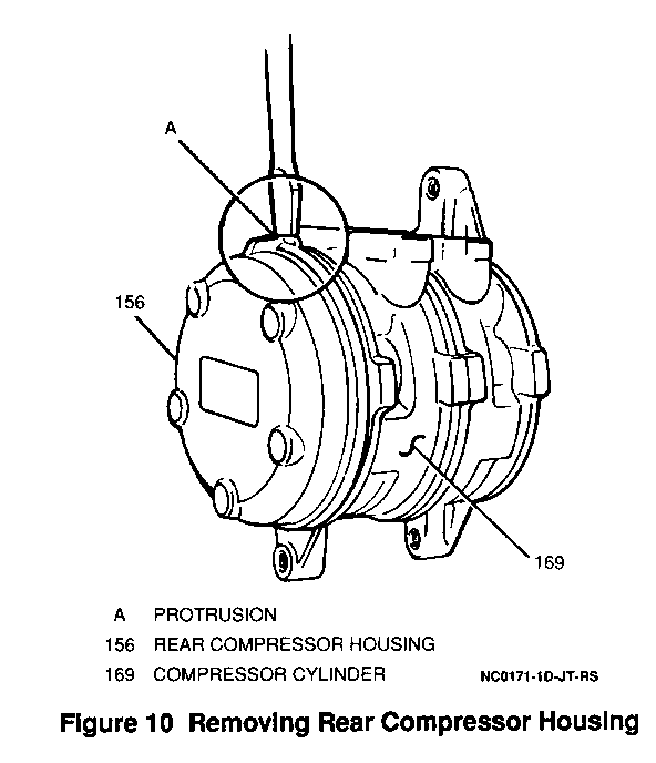
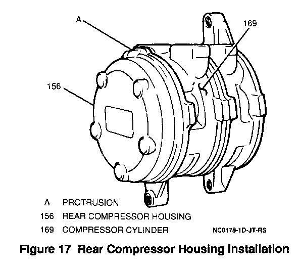
11. Rear compressor housing; pry off with a screwdriver
NOTICE:
o Be careful not to damage or scratch sealing surfaces of the front and rear housings.
12. Rear gasket and reed valve.
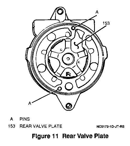
13. Two pins from rear of compressor and valve plate.
14. Rear suction plate.
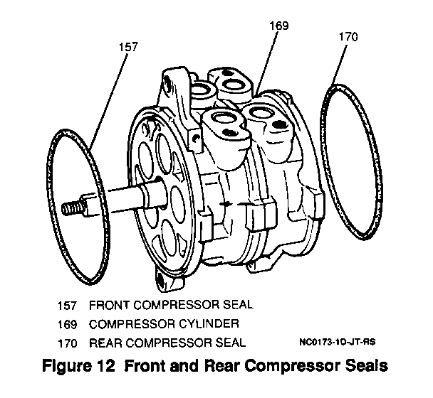
15. Figure 12 Front and Rear Compressor Seals
IMPORTANT: --------- o Do not disassemble the compressor any further. The compressor cylinder (subpump assembly) is replaced as a unit.
Clean:
o Clean all compressor parts with solvent and let dry completely. When dry, apply compressor oil to them.
Inspect:
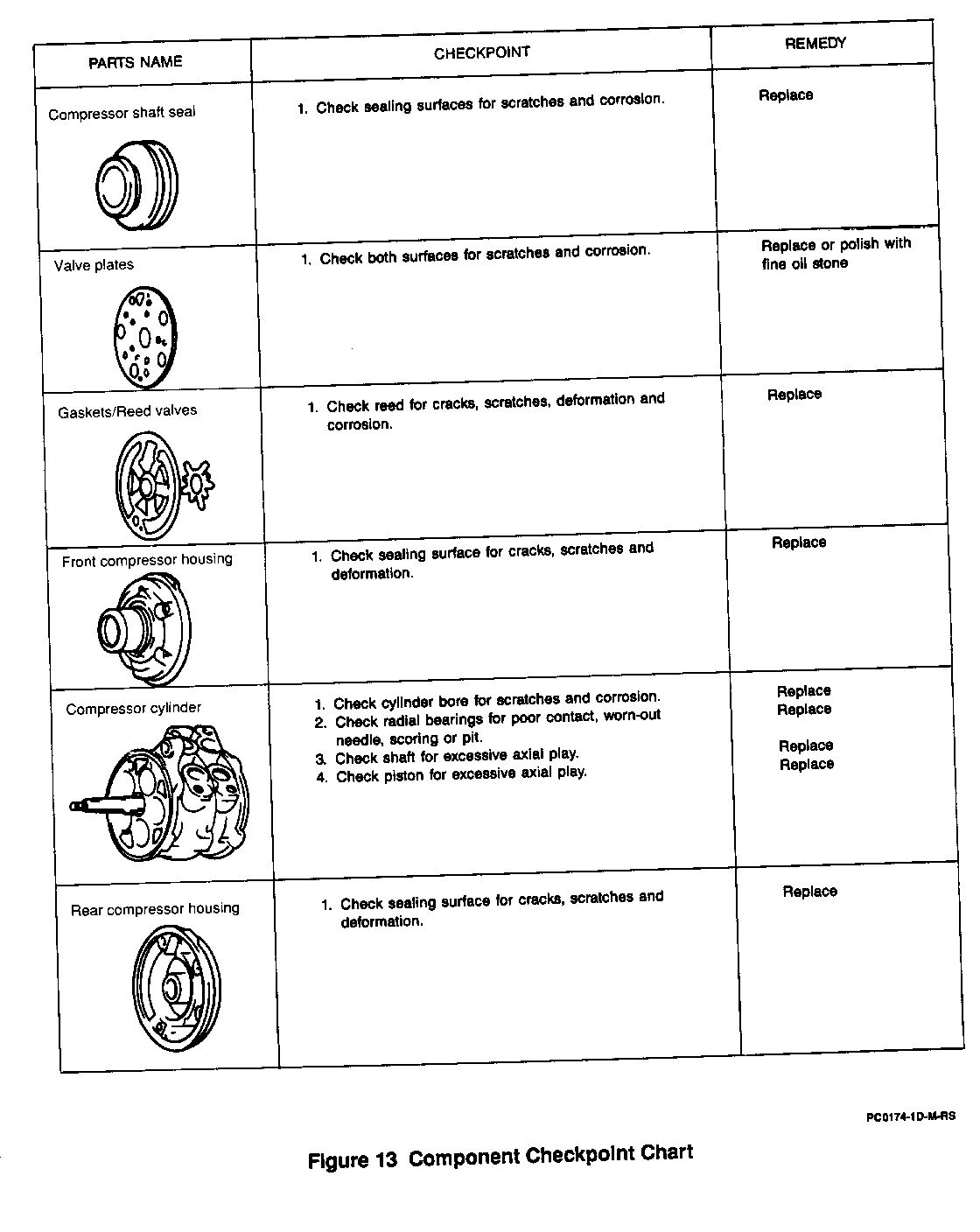
o All compressor parts that were removed. Refer to the "Component Checkpoint Chart".
Install or Connect:
o Tools Required:
o J 34614 Shaft Seal Protector
o J 33942-B Seal Seat Remover
IMPORTANT
o Do not reuse shaft seal gasket 0-rings, front or rear compressor seals, or washers. Use new washers and a compressor gasket set.
o Before beginning reassembly procedures, make sure that all parts are clean and that the work area is clean.
1. New compressor seal to rear of compressor. Lubricate seal with compressor oil.
2. Two pins on rear of compressor.
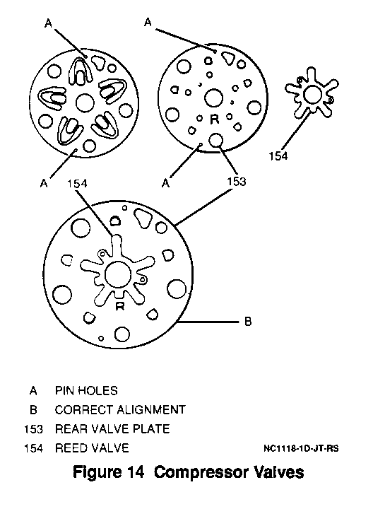
3. Suction valve, valve plate and reed valve to rear of compressor lining up the plates with the two pins.
IMPORTANT
o The front and rear suction and reed valves are identical. The front and rear valve plates are marked "F" and "R".
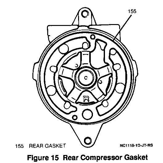
4. New rear gasket; lubricate with compressor oil prior to installation
IMPORTANT
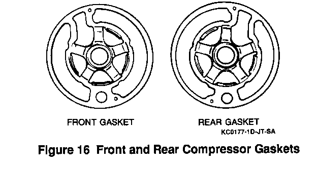
o The front and rear gaskets are different (Figure 16). Do NOT interchange them. Assemble gaskets so that their protruded surfaces face upward.
5. Rear housing to compressor.
6. New compressor seal to front of compressor. Lubricate seal with compressor oil.
7. Two pins on front of compressor.
8. Suction valve, valve plate and reed valve to front of compressor, lining up the plates with the two pins.
9. New front compressor gasket; lubricate with compressor oil prior to installation .
10. Front compressor housing and five through bolts and new washers
IMPORTANT
o Do NOT reuse the five old front housing washers.
Tighten:
o Compressor through bolts to 27 N.m (20 Lb.Ft.).
11. Compressor shaft seal.
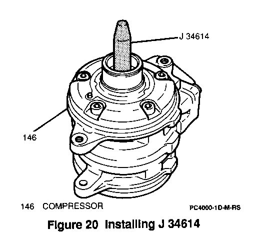
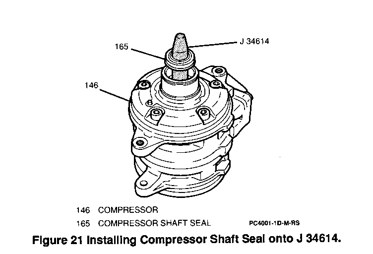
A. Coat the J 34614 with compressor oil and install onto compressor shaft
B. Apply compressor oil to shaft seal 0-ring and install compressor shaft seal onto J 34614 (when fitting the shaft seal onto the J 34614, be sure to have the 0-ring facing down).
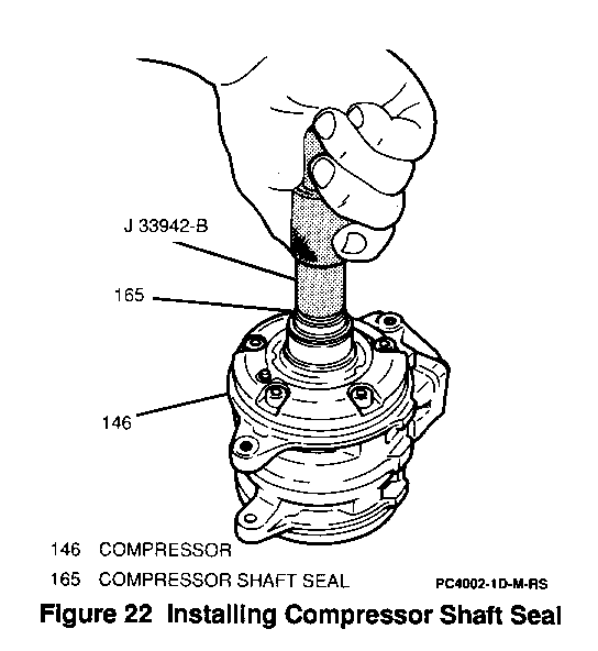
C. Place the J 33942-B onto the shaft seal.
NOTICE:
o Do NOT use a press, hammer or other similar tools to press the J 33942-B or shaft seal into place. Damage to the compressor or compressor shaft seal may occur. D. Using hand pressure only, slowly press the J 33942-B to seat the shaft seal (the shaft seal upper face must be beneath the snap ring fitting groove when seated)
12. New snap ring using snap ring pliers.
13. New oil felt and retainer inside the bore.
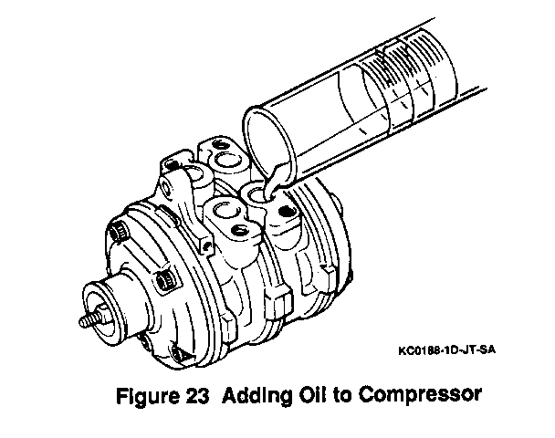
o Pour new compressor oil into compressor through service valve opening. Add the same amount of oil that was removed at the beginning of the overhaul procedure.
IMPORTANT: --------- o If a new compressor is being installed, it is shipped from the factory with 80 ml (2.7 FL.OZ.) of compressor oil in it. Drain 40 ml (1.4 FL.OZ.) of oil from the new compressor before installation, as that much oil remains in other components within the vehicle's refrigeration system.
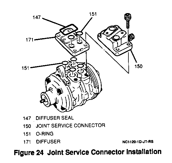
14. Joint service connector. Lubricate new 0-rings with compressor oil.
Tighten:
o Four joint service connector bolts to 27 N.m (20 LB.FT.).
IMPORTANT: --------- o The suction port has a larger internal opening than the discharge port. The 0-rings are not interchangeable.
15. A/C compressor clutch. Refer to "A/C Compressor Clutch" earlier in this section.
Inspect:
o Compressor shaft rotating torque. Torque should be less than 3 N.m (27 LB.IN.).
General Motors bulletins are intended for use by professional technicians, not a "do-it-yourselfer". They are written to inform those technicians of conditions that may occur on some vehicles, or to provide information that could assist in the proper service of a vehicle. Properly trained technicians have the equipment, tools, safety instructions and know-how to do a job properly and safely. If a condition is described, do not assume that the bulletin applies to your vehicle, or that your vehicle will have that condition. See a General Motors dealer servicing your brand of General Motors vehicle for information on whether your vehicle may benefit from the information.
