GM Service Manual Online
For 1990-2009 cars only

Removal Procedure

Caution: Do NOT remove an air supply pipe in an attempt to depressurize the air suspension. Always follow the Air Suspension Depressurization Procedure in Air Suspension. Failure to follow this procedure may cause personal injury or damage to the vehicle.

  1. Depressurize the air suspension system. Refer to Air Suspension Depressurization .
  2. Raise and support the vehicle. Refer to Lifting and Jacking the Vehicle in General Information.
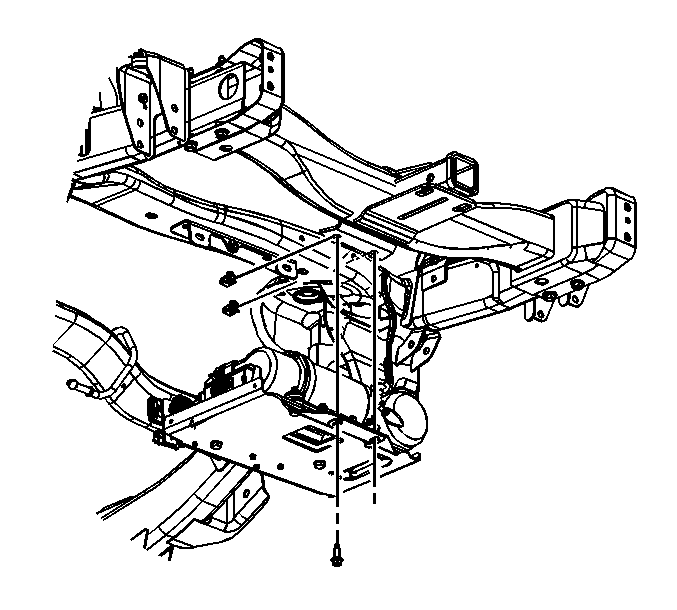
  3. Support the compressor assembly with a suitable stand.

  4. Object Number: 797658  Size: SH
  5. Disconnect the air inflator switch electrical connector.
  6. Disconnect the compressor electrical connector.
  7. Disconnect the ground strap.

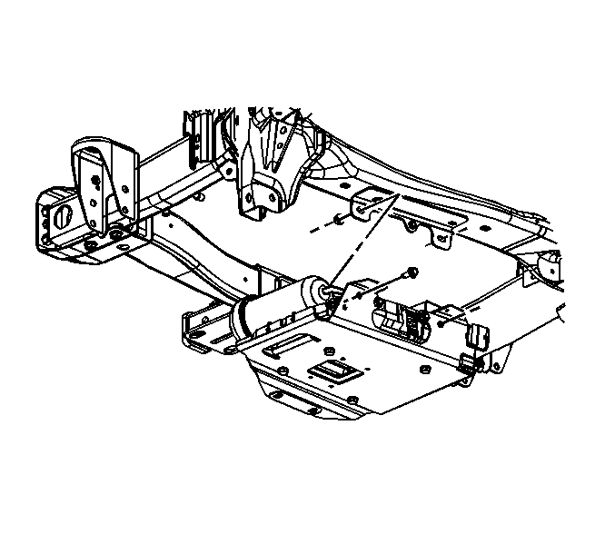
  8. Object Number: 797663  Size: SH
  9. Remove the rear compressor mounting bolts.

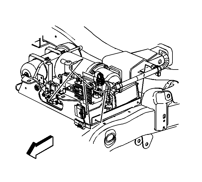
  10. Object Number: 821950  Size: SH
  11. Remove the front compressor mounting bolts.
  12. Important: Note the port location of the air lines for reassembly.

  13. Lower the compressor assembly to access the air lines then disconnect the air lines. Refer to Air Suspension Air Line Replacement .
  14. Remove the compressor assembly from the vehicle.
  15. Set the compressor assembly on a bench or suitable support.
  16. Important: Refer to the following procedures if replacing any of the compressor assemblies sub-components:

    Control Module Removal

    • Disconnect the electrical connection.
    • Remove the control module retention screw.
    • Slide the control module forward and remove.

    Filter/Air Dryer Assembly Removal

    • Remove the air pipes from the filter/air dryer. Refer to Air Suspension Air Line Replacement .
    • Remove the nuts from the filter/air dryer assembly.
    • Remove the filter/air dryer.

    Air Valve Manifold Assembly Removal

    • Unlock and disconnect the electrical connector from the pressure transducer/sensor by turning the connection counter clockwise.
    • Remove the air pipes. Refer to Air Suspension Air Line Replacement .
    • Remove the pigtail harness from the compressor assembly mounting bracket.
    • Remove the mounting screws.
    • Remove the Air Valve Manifold Assembly.

    Compressor Removal; includes exhaust valve

    • Remove the filter/air dryer.
    • Disconnect the electrical connection.
    • Remove the electrical harness from the compressor assembly mounting bracket.
    • Remove the compressor mounting nuts and bolts.
    • Remove the compressor.

    Isolator Removal

    • Remove the isolator bolts.
    • Remove the isolators.

Installation Procedure

    Notice: Refer to Fastener Notice in the Preface section.

  1. Set the compressor assembly on a bench or suitable support.
  2. Important: Refer to the following procedures if reinstalling any of the compressor assembly sub-components:

    Control Module Replacement

    • Slide the control module rearward to install.
    • Install the control module retention screw.

    Tighten
    Tighten the screw to 2.5 N·m (22 lb in).

    • Connect the electrical connection.

    Filter/Air Dryer Assembly Replacement

    • Install the filter/air dryer.
    • Install the nuts to the filter/air dryer assembly.

    Tighten
    Tighten the nuts to 12 N·m (106 lb in).

    • Install the air pipes to the filter/air dryer. Refer to Air Suspension Air Line Replacement .

    Air Valve Manifold Assembly Replacement

    • Install the Air Valve Manifold Assembly.
    • Install the mounting screws.

    Tighten
    Tighten the screw to 3.5 N·m (31 lb in).

    • Install the pigtail harness to the compressor assembly mounting bracket.
    • Connect and lock the electrical connector to the pressure transducer/sensor by turning the connection clockwise.
    • Install the air pipes. Refer to Air Suspension Air Line Replacement .

    Compressor Replacement; includes exhaust valve

    • Install the compressor.
    • Install the compressor mounting nuts and bolts.

    Tighten
    Tighten the nuts to 20 N·m (15 lb ft).

    • Install the electrical harness to the compressor assembly mounting bracket.
    • Connect the electrical connection.
    • Install the filter/air dryer.

    Isolator Replacement

    • Install the isolators.
    • Install the isolator bolts.

    Tighten
    Tighten the nuts to 20 N·m (15 lb ft).

    Important: Check the air supply lines for deep scores or cuts. If the air supply lines are damaged the lines must be replaced.

  3. Install the air lines.

  4. Object Number: 797663  Size: SH
  5. Install the front air spring compressor mounting bolts.
  6. Tighten
    Tighten the bolts to 50 N·m (37 lb ft).

    Object Number: 821950  Size: SH
  7. Install the rear air spring compressor mounting bolts.
  8. Tighten
    Tighten the bolts to 50 N·m (37 lb ft).

    Object Number: 797658  Size: SH
  9. Connect the air spring compressor electrical connector.
  10. Connect the ground strap.
  11. Tighten
    Tighten the bolt to 6 N·m (53 lb in).

  12. Connect the air inflator switch electrical connector.
  13. Remove the support from the compressor
  14. Important: If the rear axle was allowed to hang unsupported, lower the vehicle far enough to allow the air spring to be manually engaged to the support on the axle tube with minimal distortion of the air spring bladder. Ensure that the air spring is fully engaged to the axle support.

  15. Pressurize the air springs. Refer to Air Suspension Pressurization .
  16. Perform the suspension position calibration procedure. Refer to Suspension Position Calibration .
  17. Check for leaks. If a leak is found at the air supply line connections replace the air supply lines. Refer to Air Suspension Air Line Replacement .