Tools Required
J 45754 Pinion Bearing Race Remover/Installer - 9.25 in Axle
- Before assembly, apply axle lubricant to the following parts. Use the proper fluid. Refer to Sealers, Adhesives, and Lubricants .
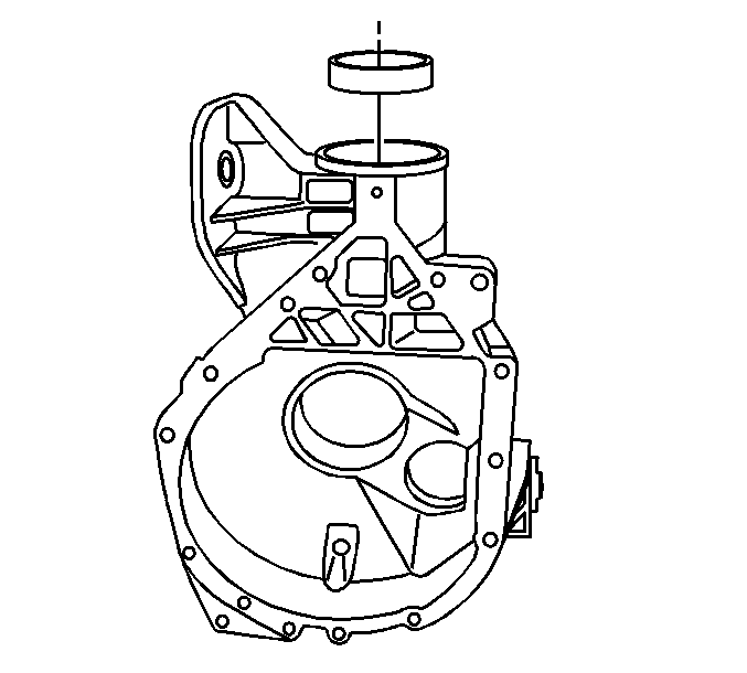
- Install the outer pinion bearing cup into the outer pinion bearing cup bore.
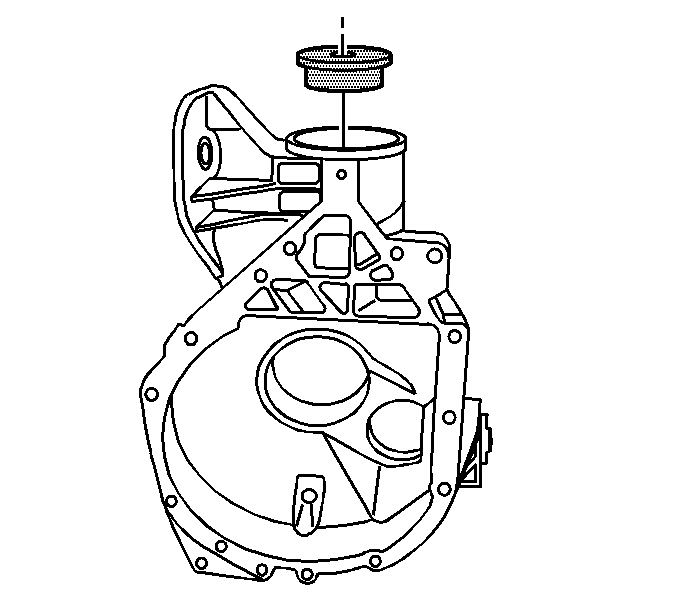
- Install the J 45754-1 over the outer pinion bearing cup.
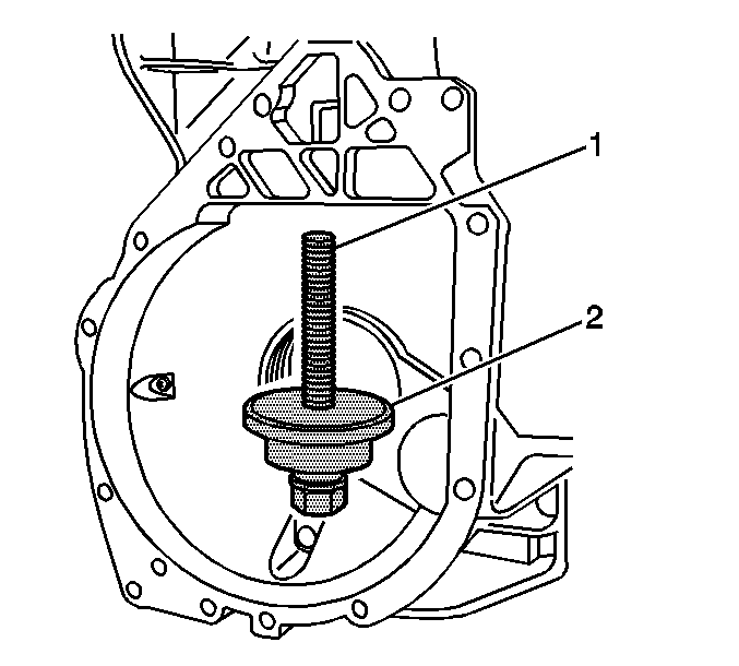
- Install the forcing screw (1), the J 45754-2 (2) into the inner pinion bearing cup bore.
- Attach the forcing screw to the J 45754-1.
- Turn the forcing screw clockwise slowly in order to draw the outer pinion bearing cup into the outer pinion bearing cup bore.
- Tighten the forcing screw until the outer pinion bearing cup is seated in the outer pinion bearing cup bore.
- Remove the J 45754 .
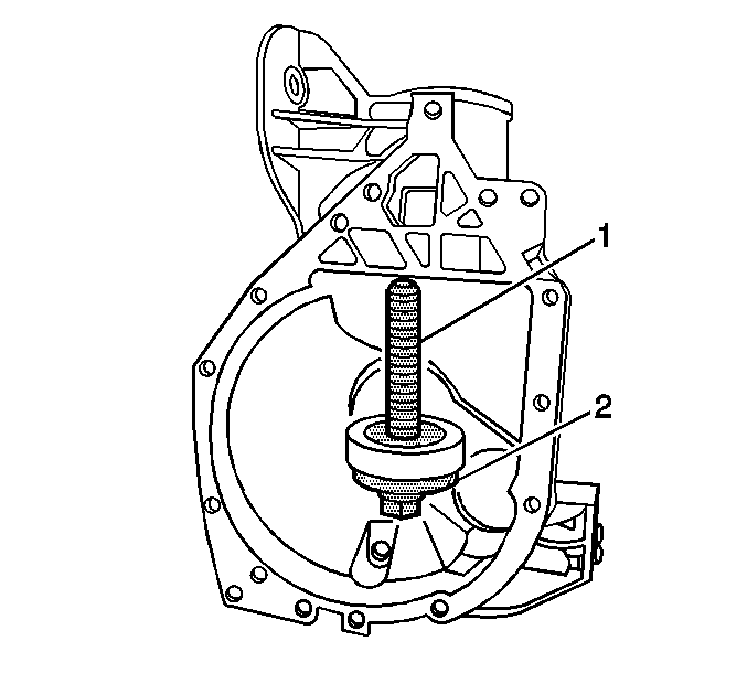
- Install the inner pinion bearing cup onto the J 45754-2 (2) and the forcing screw (1).
- Install the J 45754-2 (2), the forcing screw (1), and the inner pinion bearing cup into the pinion bearing cup bore.
- Install the J 45754-1 over the outer pinion bearing cup.
- Attach the forcing screw to the J 45754-1.
- Turn the forcing screw clockwise slowly in order to draw the inner pinion bearing cup into the inner pinion bearing cup bore.
- Tighten the forcing screw clockwise until the inner pinion bearing cup is seated in the inner pinion bearing cup bore.
- Remove the J 45754 .
- Measure the pinion depth and determine the selectable pinion shim thickness. Refer to Pinion Depth Adjustment .
| • | The pinion bearings |
| • | The pinion and the differential gears |
| • | The thrust washers |
| • | The pinion bearing cups |


Slowly turn the forcing screw until the J 45754-1 is evenly seated over the outer pinion bearing cup bore and the J 45754-2 with the inner pinion bearing cup is evenly seated over the inner pinion bearing cup bore.
Inspect the position of the outer pinion bearing cup as it is being drawn into the outer pinion bearing cup bore to ensure the bearing cup is being pulled straight into the pinion bearing cup bore. If the pinion bearing cup is not being pulled straight into the bearing cup bore, remove the J 45754 and the outer pinion bearing cup and reposition the outer pinion bearing cup.


Slowly turn the forcing screw until the J 45754-1 is evenly seated over the outer pinion bearing cup bore and the J 45754-1 with the inner pinion bearing cup is evenly seated over the inner pinion bearing cup bore.
Inspect the position of the inner pinion bearing cup as it is being drawn into the inner pinion bearing cup bore to ensure the bearing cup is being pulled straight into the pinion bearing cup bore. If the pinion bearing cup is not being pulled straight into the bearing cup bore, remove the J 45754 and the inner pinion bearing cup and reposition the inner pinion bearing cup.
