Tools Required
| • | J 25025-1 Dial Indicator Mounting Post |
| • | J 39855 Stator Shaft Seal Installer |
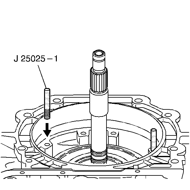
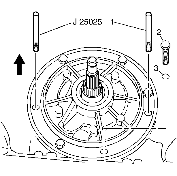
- Install the J 25025-1 .
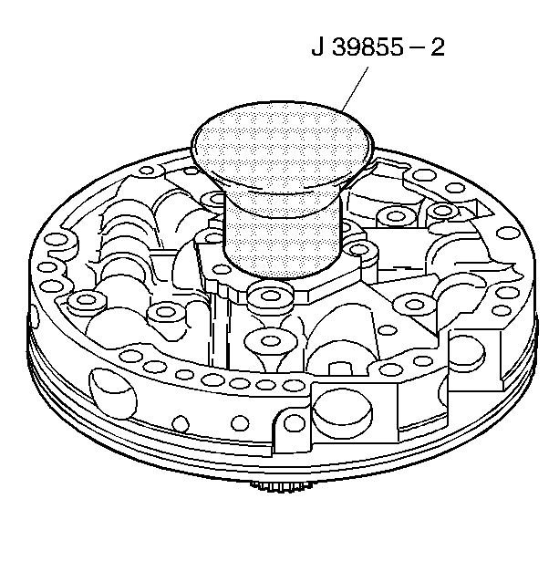
- Remove the J 39855-2 which is part of kitJ 39855 .
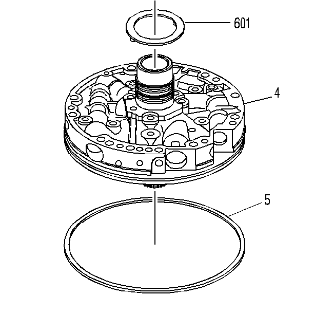
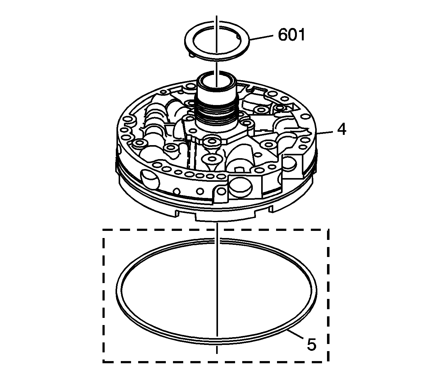
- Install the pump to drum thrust washer (601).
- Use J 36850 or equivalent to retain the washer to the pump.
- Install the oil pump to case seal (5) on the oil pump assembly (4).
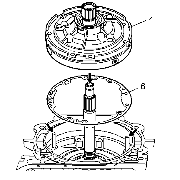
- Install the pump cover to case gasket (6).
- Install the oil pump assembly (4) into the case and align all holes properly.
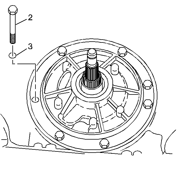
- Install the pump to case bolts (2) with new O-ring seals (3).
- Remove the J 25025-1 .
- Install the remaining pump to case bolts (2) and O-ring seals (3), in the holes where theJ 25025-1 were.
Notice: Use the correct fastener in the correct location. Replacement fasteners must be the correct part number for that application. Fasteners requiring replacement or fasteners requiring the use of thread locking compound or sealant are identified in the service procedure. Do not use paints, lubricants, or corrosion inhibitors on fasteners or fastener joint surfaces unless specified. These coatings affect fastener torque and joint clamping force and may damage the fastener. Use the correct tightening sequence and specifications when installing fasteners in order to avoid damage to parts and systems.
Important: The pump to case bolt O-ring seals (3) must be replaced.
Tighten
Tighten the bolts to 29 N·m (21 lb ft).
Tighten
Tighten the bolts to 29 N·m (21 lb ft).
Tools Required
| • | J 25025-1 Dial Indicator Mounting Post |
| • | J 39855 Stator Shaft Seal Installer |
- Install the J 25025-1 .
- Remove the J 39855-2 which is part of kit J 39855 .
- Install the pump to drum thrust washer (601).
- Use J 36850 or equivalent to retain the washer to the pump.
- Install the oil pump o-ring seal into the oil pump o-ring groove - some models.
- Install the pump cover to case gasket (6).
- Install the oil pump assembly (4) into the case and align all holes properly.
- Install the pump to case bolts (2) with new O-ring seals (3).
- Remove the J 25025-1 .
- Install the remaining pump to case bolts (2) and O-ring seals (3), in the holes where the J 25025-1 were.




Notice: Use the correct fastener in the correct location. Replacement fasteners must be the correct part number for that application. Fasteners requiring replacement or fasteners requiring the use of thread locking compound or sealant are identified in the service procedure. Do not use paints, lubricants, or corrosion inhibitors on fasteners or fastener joint surfaces unless specified. These coatings affect fastener torque and joint clamping force and may damage the fastener. Use the correct tightening sequence and specifications when installing fasteners in order to avoid damage to parts and systems.
Important: The pump to case bolt O-ring seals (3) must be replaced.
Tighten
Tighten the bolts to 29 N·m (21 lb ft).

Tighten
Tighten the bolts to 29 N·m (21 lb ft).
