Spare Tire Carrier Replacement SUV
Removal Procedure
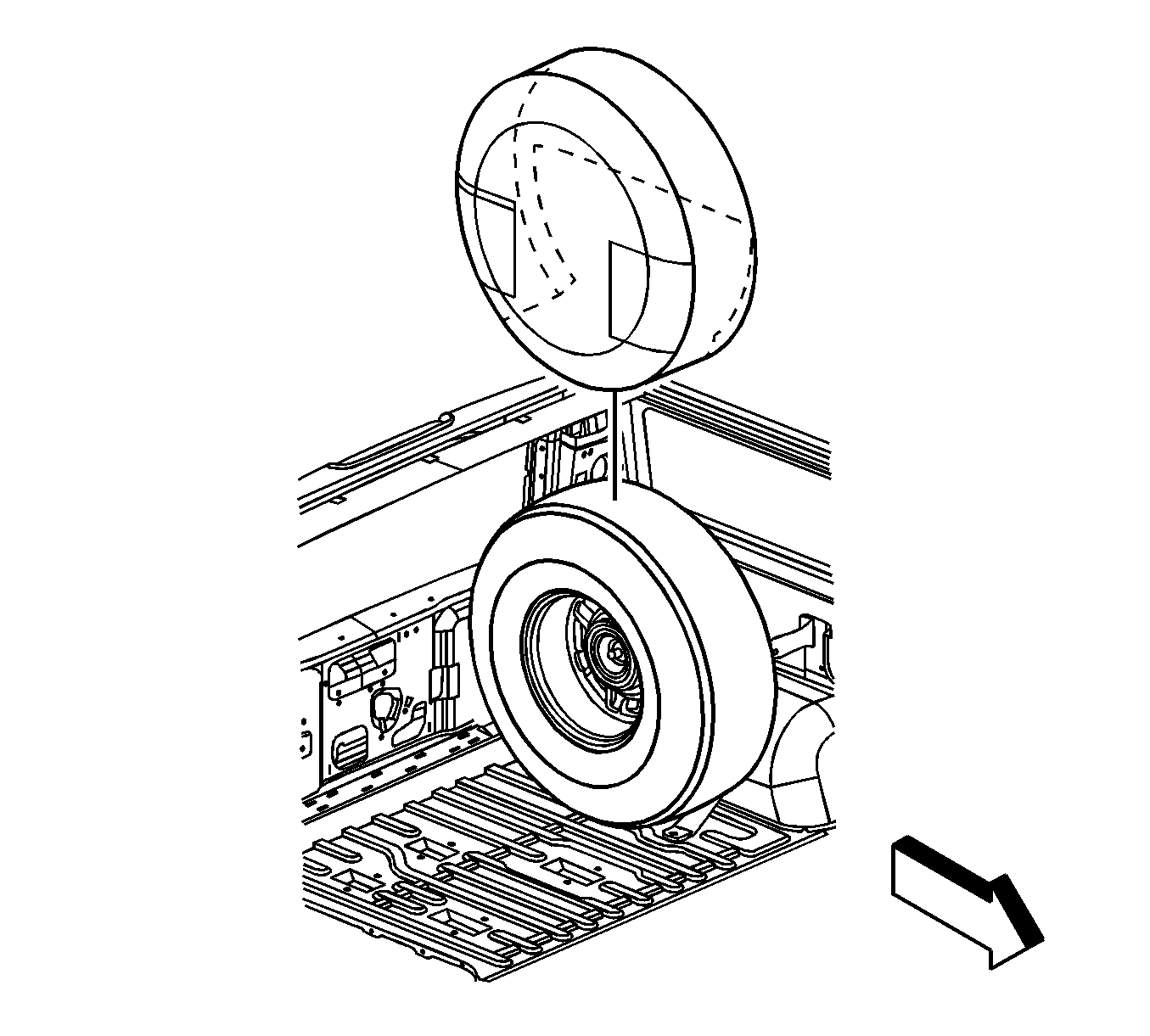
- Remove the spare tire cover.
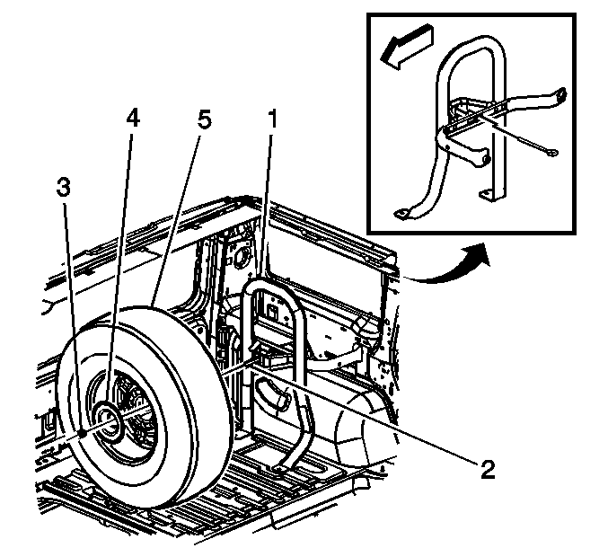
- Remove the spare tire mounting nut (3), washer, and mounting plate (4).
- Remove the spare tire (5) from the spare tire carrier (1).
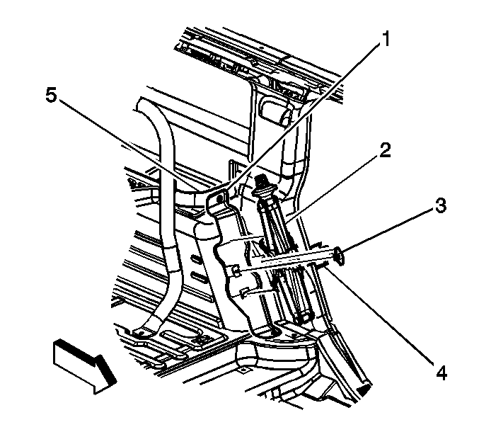
- Remove the jack retainer nut (3) and bracket (4).
- Remove the jack (2) from the jack stowage bracket assembly (1).
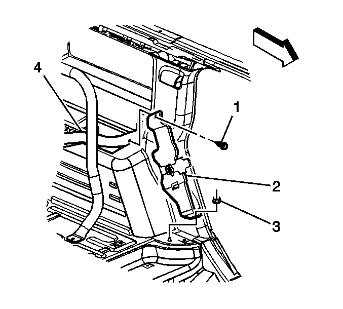
- Remove the screw (1) securing the jack stowage bracket assembly (2) to the spare tire carrier (4).
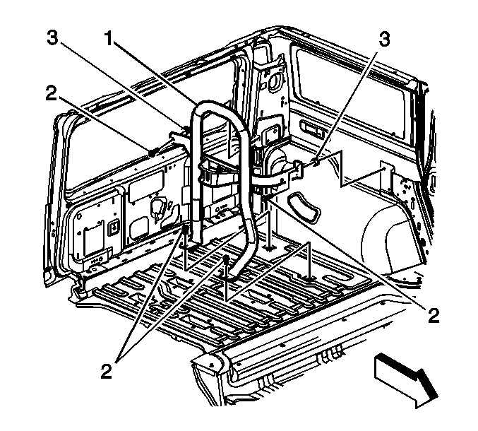
- Remove the spare tire carrier mounting bolts (2) and spacers (3).
- Remove the spare tire carrier (1) from the vehicle.
Installation Procedure
- Install the spare tire carrier (1) to the vehicle.
- Install spacers (3) and the spare tire carrier mounting bolts (2).
- Install the screw (1) securing the jack stowage bracket assembly (2) to the spare tire carrier (4).
- Install the jack (2) to the jack stowage bracket assembly (1).
- Install the jack bracket (4) and the nut (3).
- Raise the jack after it is installed in the bracket to ensure that it is secure.
- Install the spare tire (5) to the spare tire carrier (1), inserting the stud (2) through the center of the spare tire.
- Install the mounting plate (4), washer, and mounting nut (3) .
- Install the spare tire cover.

Notice: Refer to Fastener Notice in the Preface section.
Tighten
Tighten the spare tire carrier mounting bolts to
85 N·m (63 lb ft).

Tighten
Tighten the jack stowage bracket screw to 25 N·m
(18 lb ft).


Tighten
Tighten the spare tire mounting nut to 85 N·m
(63 lb ft).

Spare Tire Carrier Replacement SUT
Removal Procedure
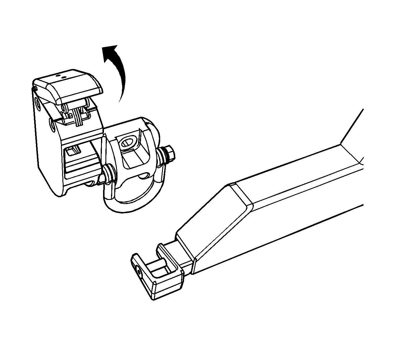
- Unlatch and open the spare tire carrier swing arm.
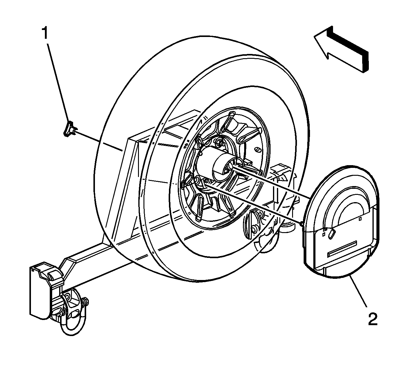
- Remove the spare tire stowage cover nut (1).
- Remove the spare tire cover (2).
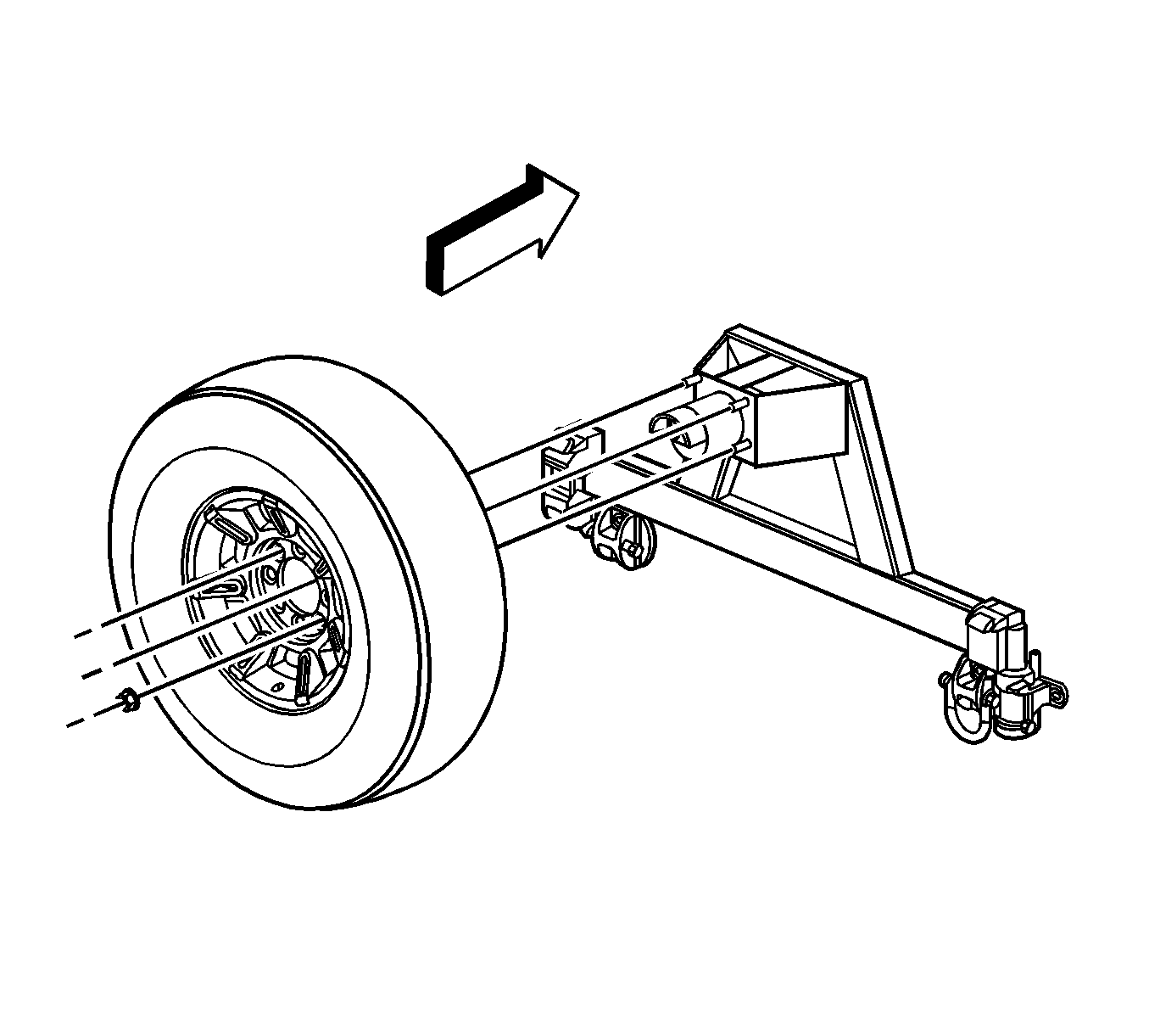
- Remove the spare tire mounting nuts.
- Remove the spare tire from the spare tire carrier.
- Remove the spare tire carrier assembly, perform the following steps:
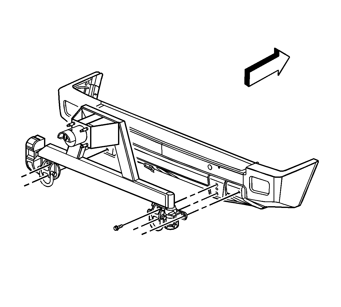
| 6.1. | Disconnect the license plate lamp harness electrical connector. |
| 6.2. | Remove the spare tire carrier bolts. |
| 6.3. | Remove the spare tire carrier assembly. |
Disassembly Procedure
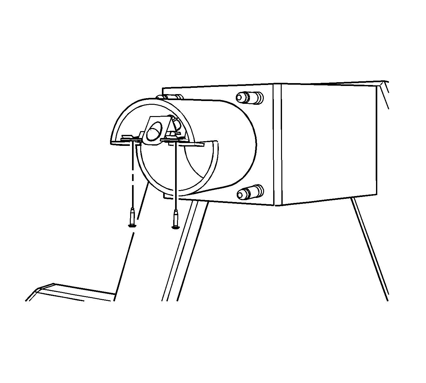
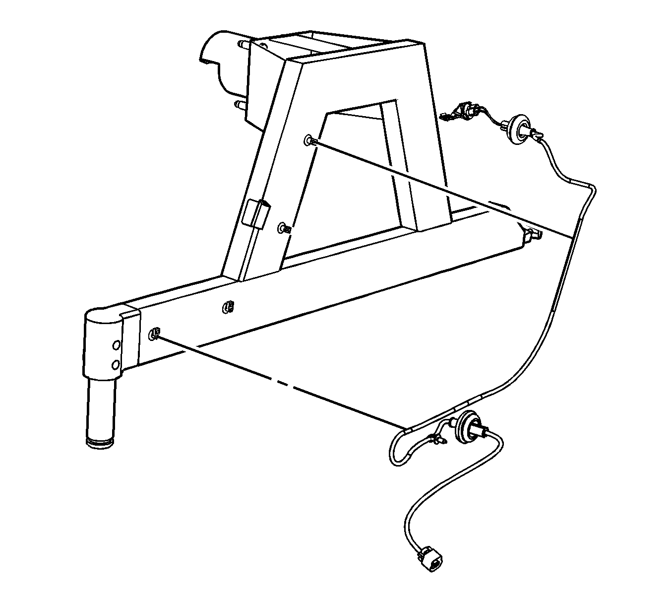
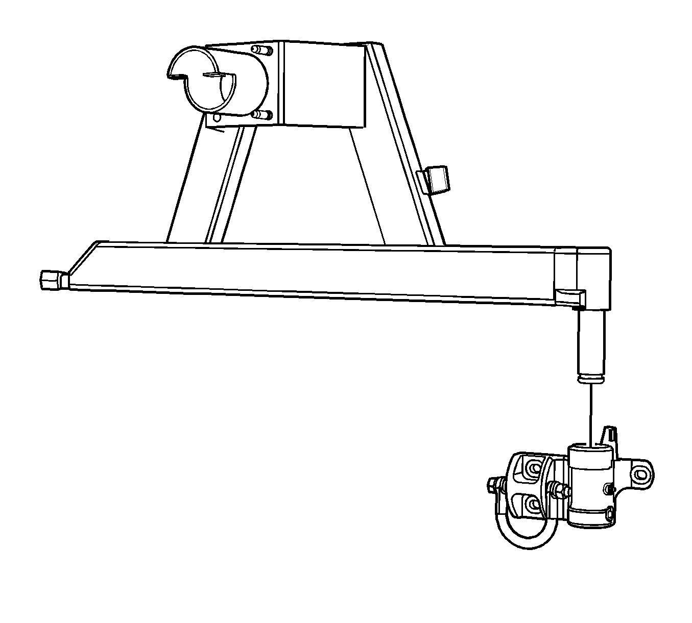
Important: The following components of the spare tire carrier can be replaced, license plate lamp harness, carrier swing arm, hinge, striker/sleeve, and latch mechanism and housing. Refer to the following information for the disassembly of the spare tire carrier. These components can either be disassembled on the vehicle or on a work bench.
- Remove the license plate lamp screws.
- Remove the license plate lamp harness from the clips on the carrier.
- Remove the harness.
- Remove the spare tire carrier swing arm from the hinge.
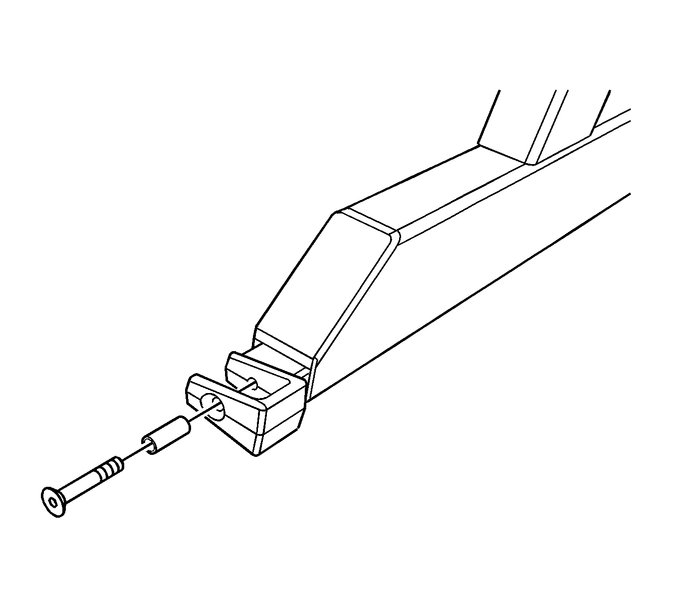
- Remove the striker bolt and sleeve.
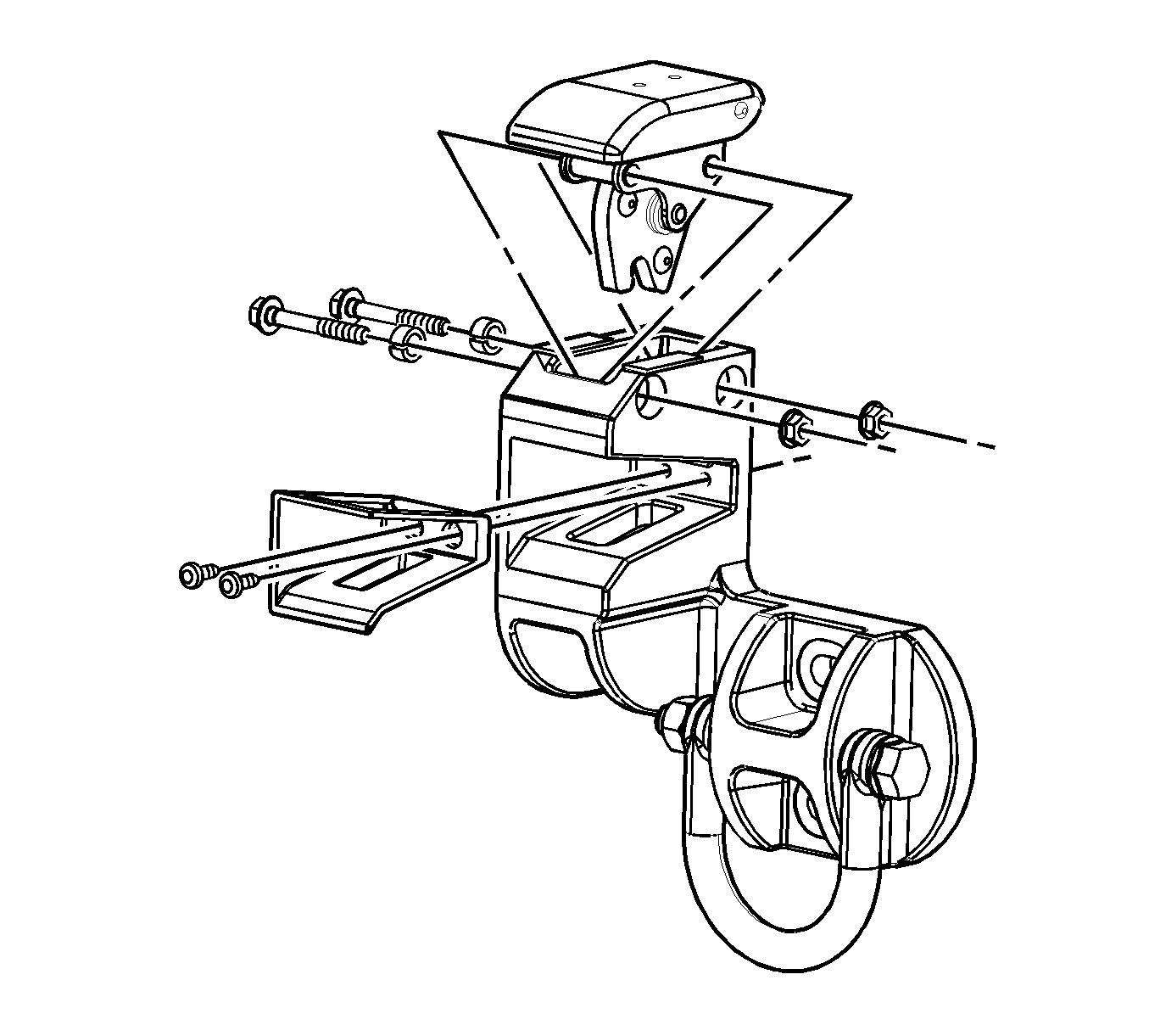
- Remove the latch mechanism bolts, nuts, and spacers.
- Remove the latch mechanism.
- Remove the latch mechanism isolator bolts.
- Remove the latch mechanism isolator.
Service/Maintenance Information
Important: The spare tire carrier requires items inspected and/or replaced at scheduled vehicle service intervals.
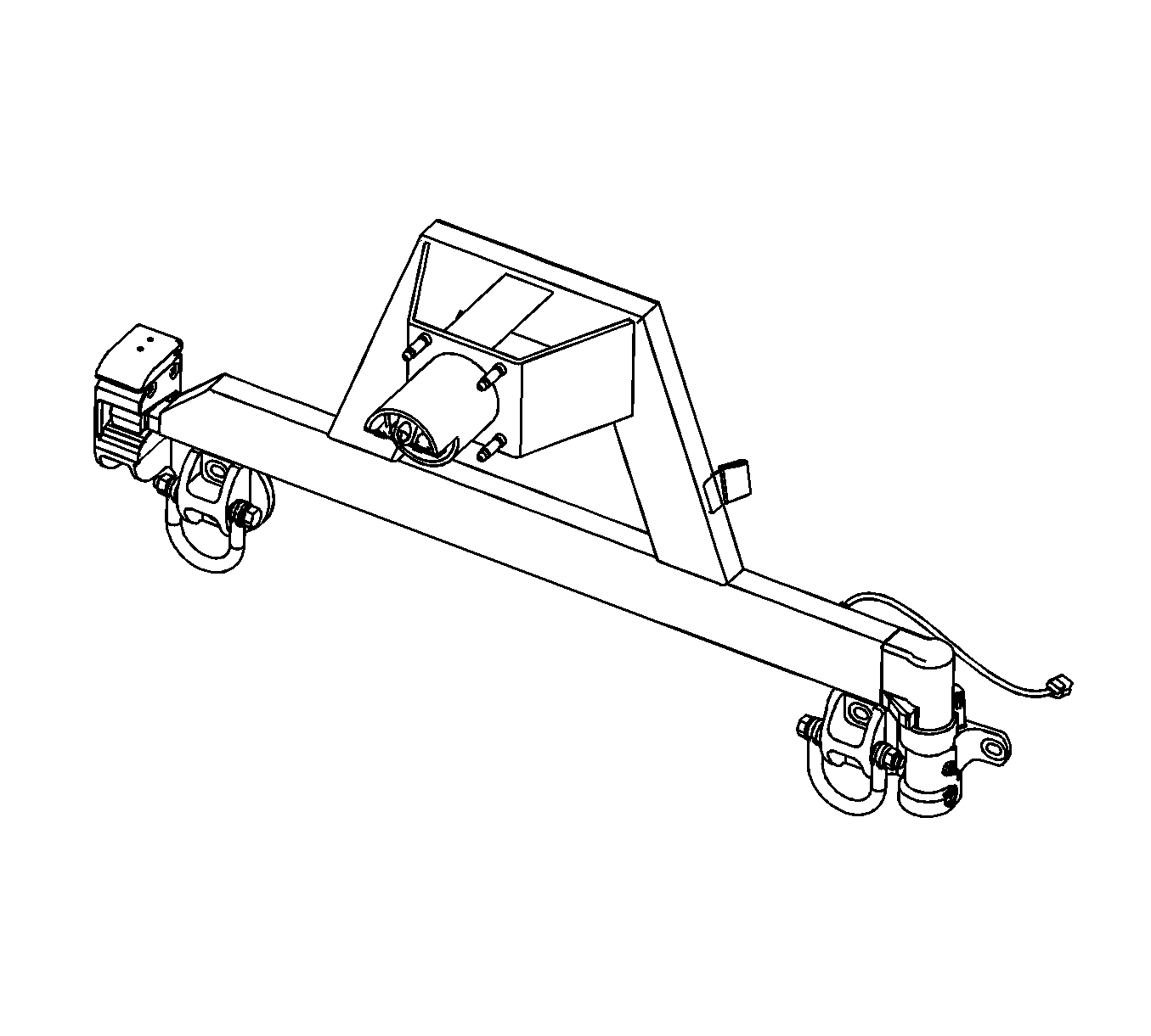
Check the carrier swing arm articulation and latching performance as follows:
| • | The swing arm closing effort is not to be excessive. |
| Adjust the latch assembly, as required. |
| • | The swing arm is to kick back beyond the latch casting after the latch handle is operated. |
| Adjust the latch assembly, as required. |
Important: Under normal conditions the hinge assembly will NOT require lubrication.
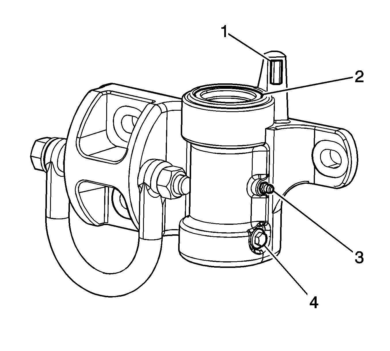
Hinge assembly--If the hinge assembly needs to be greased, due to removal, the plug needs to be removed and lubricated as stated below using GM P/N 89022180 (Canadian P/N 89022181).
- Remove the M6 set screw (4).
- Remove the 1/4 inch plug above the set screw.
- Install a grease (zerk) fitting (3) where the 1/4 inch plug was, apply grease, rotate the swing arm to ensure a uniform coating over the internal bushing.
- Once the grease is seen exiting the set screw hole: stop, reinstall the set screw (4).
- Again, grease via the zerk fitting (3), continue articulating the swing arm until grease is just visible on the casting grease seal (2). DO NOT ALLOW THE SWING ARM TO LIFT DURING LUBRICATION.
- The hinge is now primed with the correct amount of grease.
- Remove the zerk fitting (3) and reinstall the 1/4 inch plug.
- Reinstall the set screw (4).
Notice: Refer to Fastener Notice in the Preface section.
Tighten
Tighten the set screw to 9 N·m (80 lb in).
If the swing arm lifts, remove the set screw (4) and apply downward pressure while rotating the swing arm. Continue until the swing arm makes contact with the casting.
Tighten
Tighten the set screw and plug to 9 N·m (80 lb in).
Hinge assembly--Visually check the grease seal (2) for damage, replace as required.
Hinge assembly--Check the hard stop pad (1), replace as required.
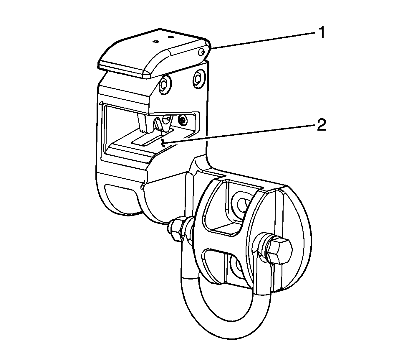
Latch assembly--Check the latch isolator (2) for damage, replace as required. Thoroughly clean the latch casting surfaces and bond the NEW isolator in place using LOCTITE Black Max 380® adhesive or equivalent.
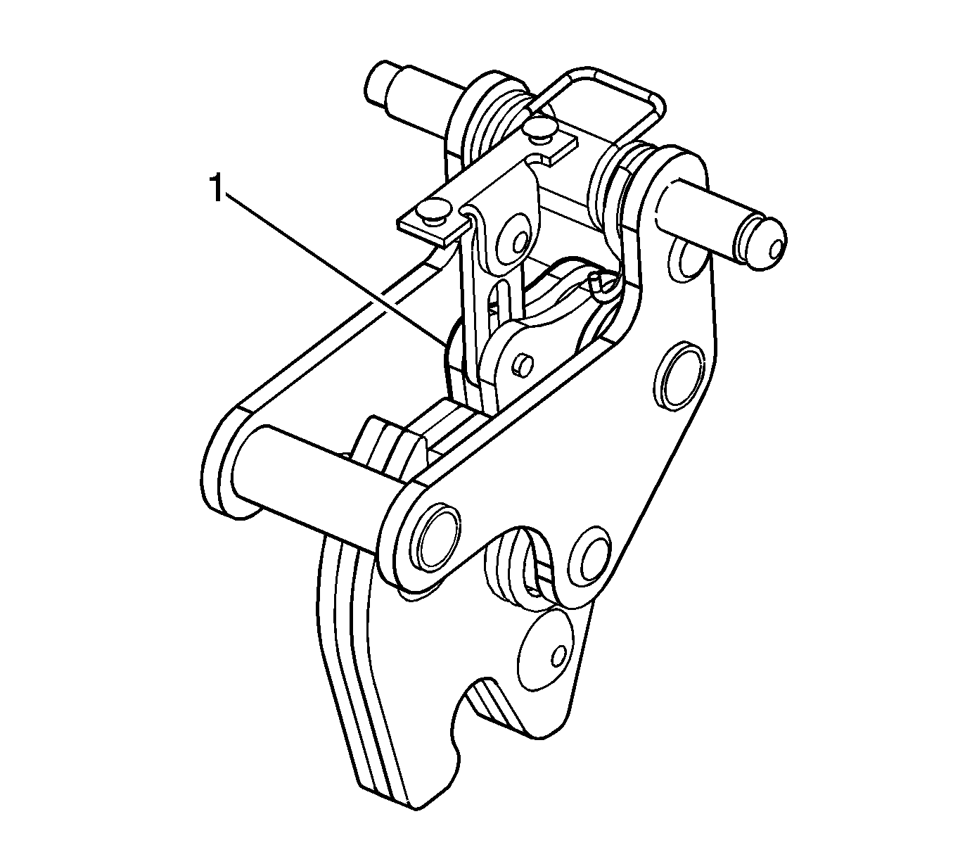
Latch assembly--Check for operation and apply Teflon dry lube GM P/N 12371287 (Canadian P/N 10953437) to the latch mechanism (1) as required.
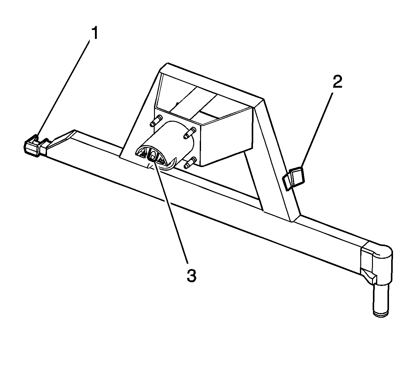
Carrier frame--Check the endgate bump stop (2) rubber for damage, replace if required. Thoroughly clean the surfaces and bond the NEW bump stop in place using LOCTITE Black Max 380® adhesive or equivalent.
Carrier frame--Check the striker sleeve (1) for wear, replace as required.
Carrier frame--Check the lamp (3) for operation.
Service Alignment Procedure
- The carrier should be loose installed to the vehicle.
- Align the latch casting square, and tighten the bolts to specifications using the sequence shown.
- Swing the carrier into the latch pocket so the striker pin touches the latch mechanism.
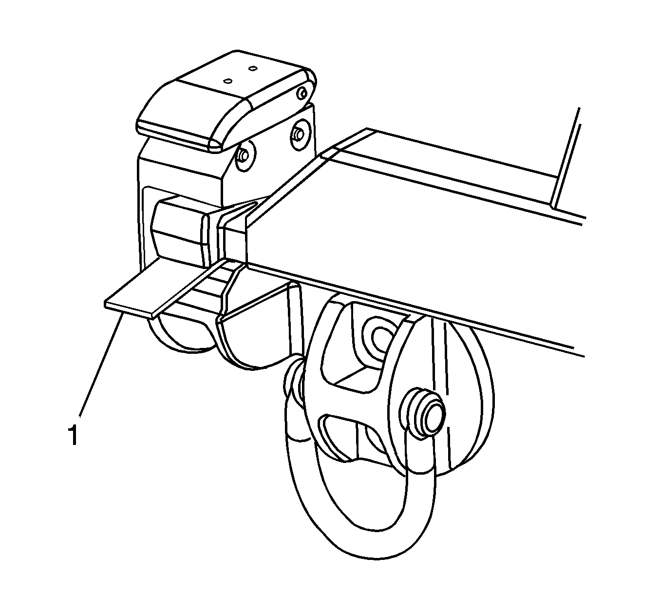
- Insert a shim (1) between the striker bottom and the latch pocket.
- Early carriers with a red striker sleeve will require a 5 mm shim, all other carriers with a yellow sleeve will require a 3 mm shim.
- Secure the hinge bolts using the specification shown above.
- Remove the shim (1), the carrier is now aligned and ready for use.
Notice: Refer to Fastener Notice in the Preface section.
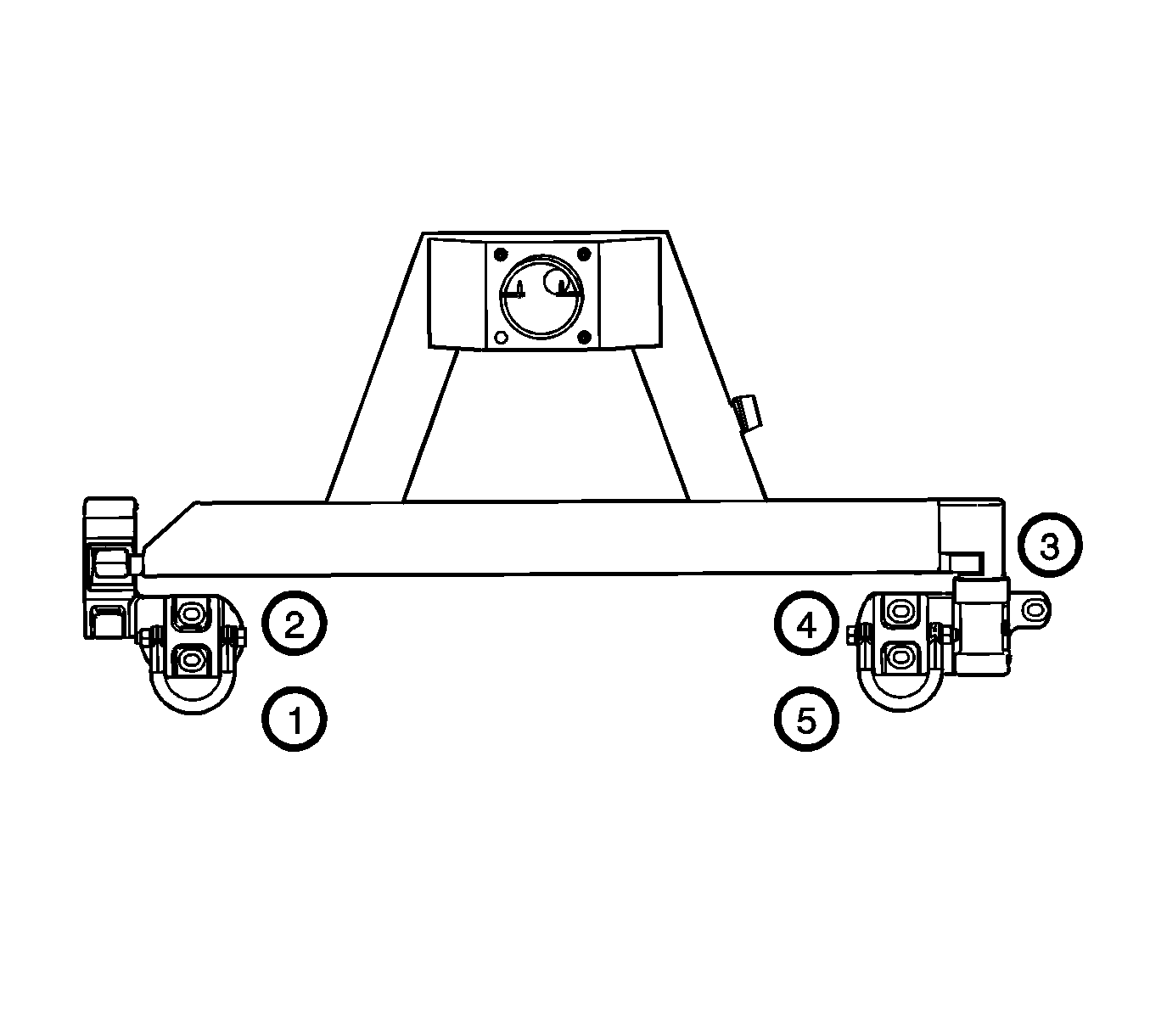
Tighten
Tighten the bolts to 95 N·m (70 lb ft).
Assembly Procedure
- Install the latch mechanism isolator, if necessary.
- Install the latch mechanism isolator screws.
- Install the latch mechanism, if necessary.
- Install the latch mechanism bolts, spacers, and nuts.
- Install the sleeve and striker bolt, if necessary.
- Install the spare tire carrier swing arm to the hinge, if necessary.
- Install the license plate lamp harness, if necessary.
- Install the license plate lamp harness to the clips on the carrier.
- Install the license plate lamp screws, if necessary.

Important: Thoroughly clean the latch casting surfaces and bond the NEW isolator in place using LOCTITE Black Max 380® adhesive or equivalent.
Tighten
Tighten the screws to 9 N·m (80 lb in).
Tighten
Tighten the bolts to 25 N·m (18 lb ft).

Tighten
Tighten the bolt to 22 N·m (16 lb ft).


Tighten
Tighten the screws to 2.5 N·m (22 lb in).
Installation Procedure
- Install the spare tire carrier to the vehicle. Perform the following steps:
- Install the spare tire to the spare tire carrier.
- Install the spare tire mounting nuts.
- Install the spare tire cover (2).
- Install the spare tire stowage cover nut (1) until snug.
- Close and ensure that the spare tire carrier is latched.

| 1.1. | Position the spare tire carrier to the rear bumper. |
| 1.2. | Loose install the carrier bolts. Refer to the Service Alignment Procedure above for alignment. |
| 1.3. | Connect the license plate lamp harness electrical connector. |

Tighten
Tighten the nuts to 95 N·m (70 lb ft).

