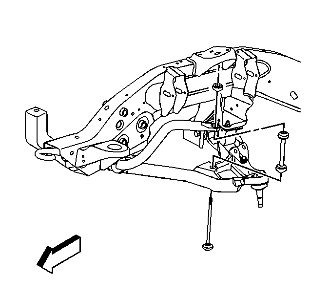
For 1990-2009 cars only
Removal Procedure
- Raise and support the vehicle. Refer to Lifting and Jacking the Vehicle in General Information.
- Remove the nuts from the link bolt assemblies.
- Remove the link bolts.
- Remove the link assemblies.

Installation Procedure
- Support the lower control arms at curb height.
- Perform the following procedure before installing the bolts:
- Install the link assemblies.
- Install the link bolts.
- Install the nuts to the link bolt assemblies.
- Lower the vehicle.

| • | Remove all traces of the original adhesive patch. |
| • | Clean the threads of the bolt with denatured alcohol or equivalent and allow to dry. |
| • | Apply threadlocker GM P/N 12345382 (Canadian P/N 10953489). |
Notice: Refer to Fastener Notice in the Preface section.
Notice: To avoid stabilizer shaft damage due to loss of clamp load, the threads of the link bolt must protrude 2 to 4 threads above the link nut after the specified torque is achieved.
Tighten
Tighten the nut to 14 N·m (10 lb ft). Continue to tighten the nut until 2-4 threads protrude above the nut.
