GM Service Manual Online
For 1990-2009 cars only
Makes
🢒
HUMMER
🢒
2007
🢒
H2
🢒
Diagnostic Navigation
🢒
Vehicle Diagnostic Information
🢒 Air Suspension Schematics
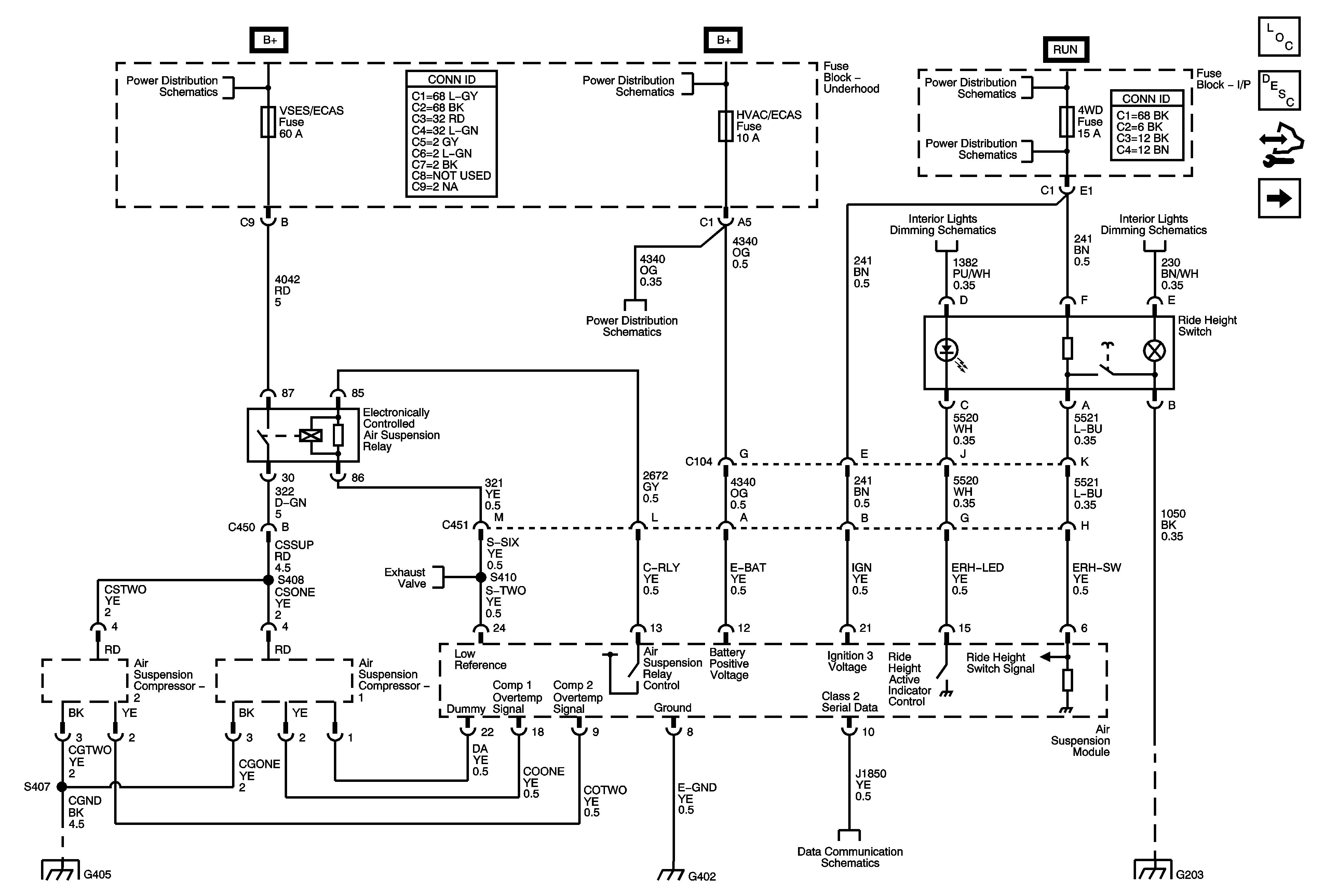
Figure
1:
Power, Ground, Serial Data, and Ride Height Switch
Master Electrical Component List
Air Suspension Description and Operation
Control Module References
Inflator Switch and Position Sensors
B+ Bus
B+ Bus
4WD, BRAKE, CRUISE, HVAC 1, and IGN 3 Fuses
Ignition Switch - ACY/RUN/START, RUN and Start Bus Bars, and CRANK and IGN A Fuses
4WD, BRAKE, CRUISE, HVAC 1, and IGN 3 Fuses
Instrument Panel Dimming - 1 of 5 and LED Dimming - 1 of 2
Instrument Panel Dimming - 3 of 5
G203 - 1 of 3
Power, Ground, DLC and Splice Pack SP205
Solenoid Valves and Ride Height Sensors
G402, G405, and G410
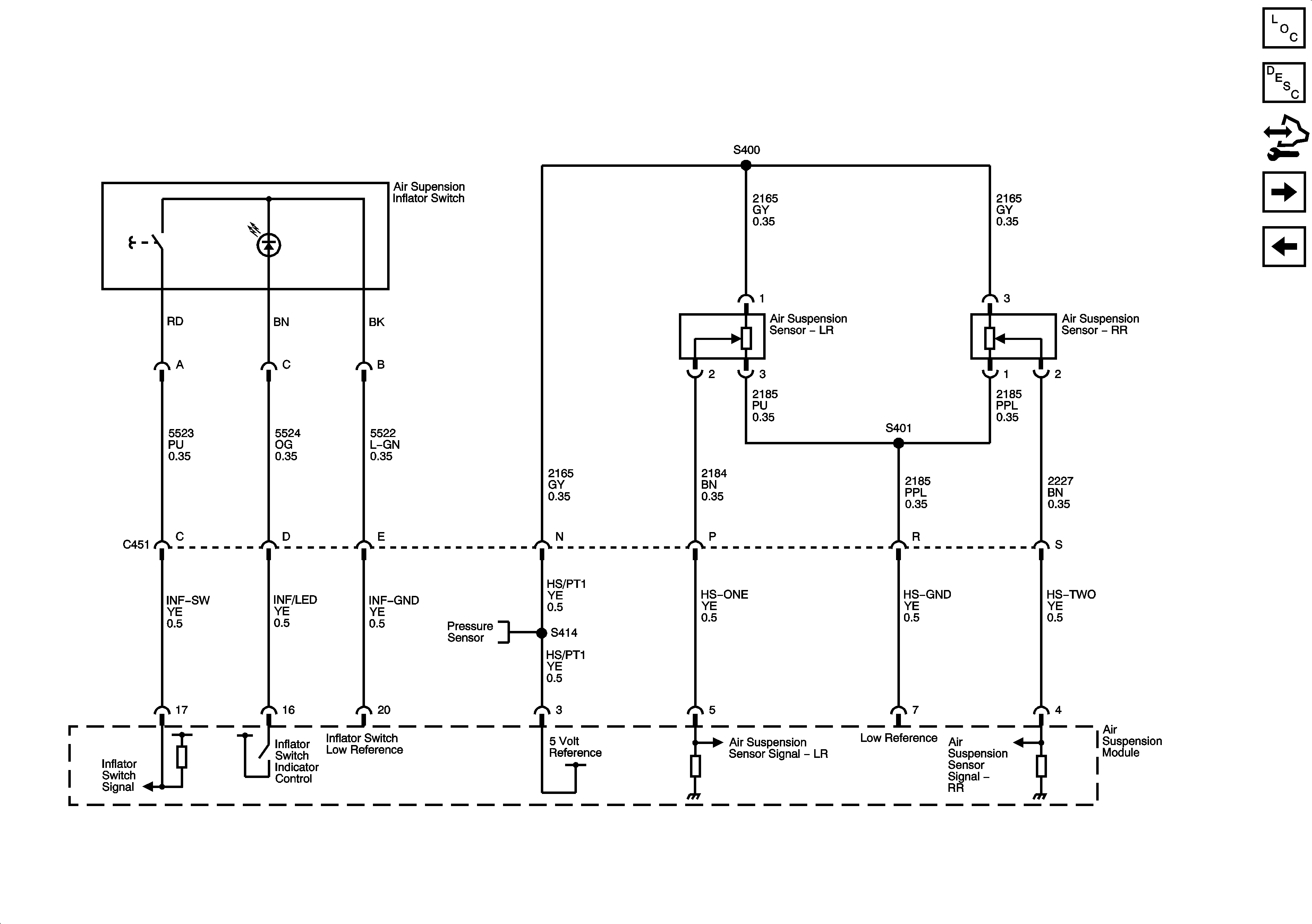
Figure
2:
Inflator Switch and Position Sensors
Master Electrical Component List
Air Suspension Description and Operation
Control Module References
Solenoid Valves and Ride Height Sensors
Power, Ground, Serial Data, and Ride Height Switch
Solenoid Valves and Ride Height Sensors
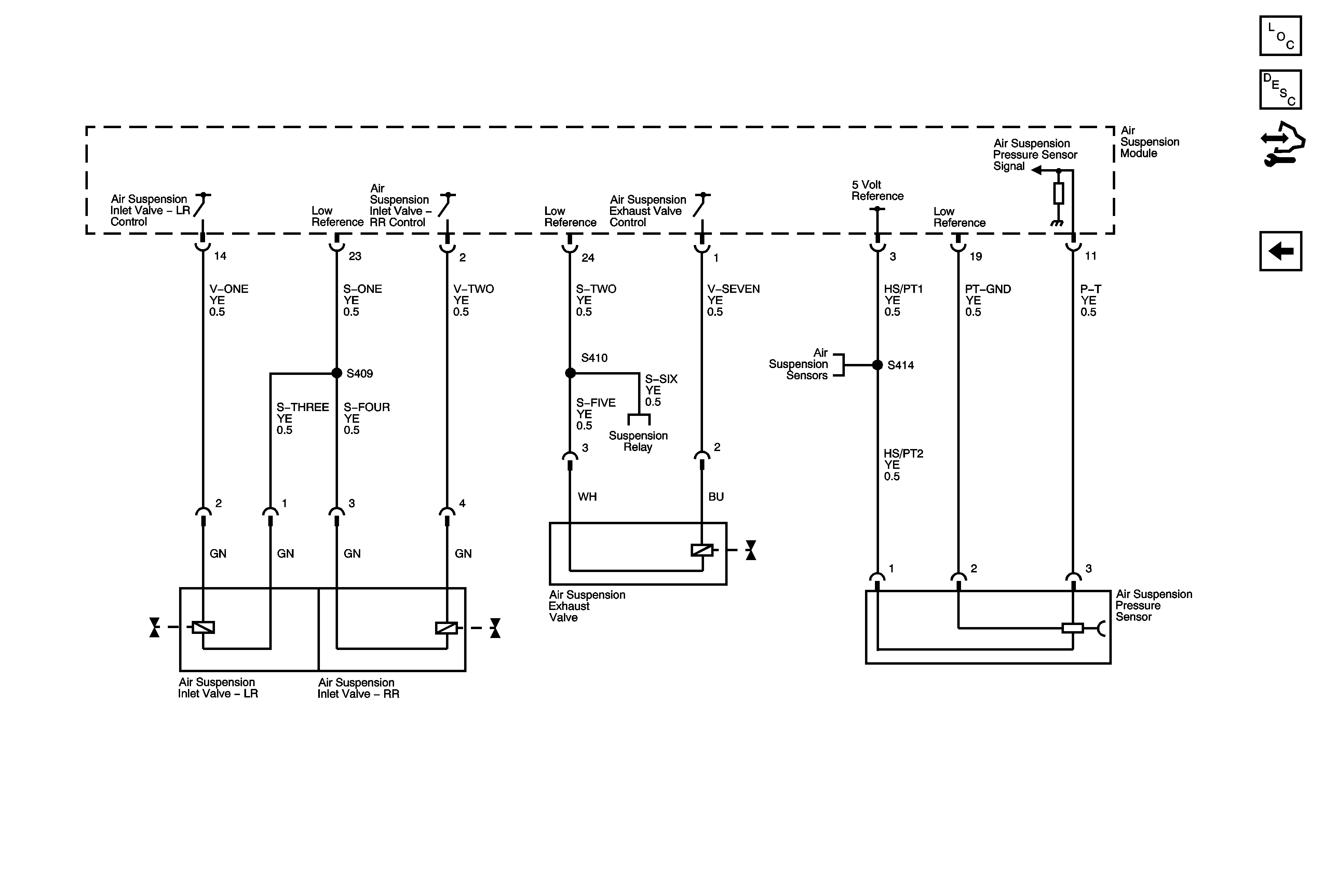
Figure
3:
Solenoid Valves and Pressure Sensors
Master Electrical Component List
Air Suspension Description and Operation
Control Module References
Inflator Switch and Position Sensors
Power, Ground, Serial Data, and Ride Height Switch
Inflator Switch and Position Sensors