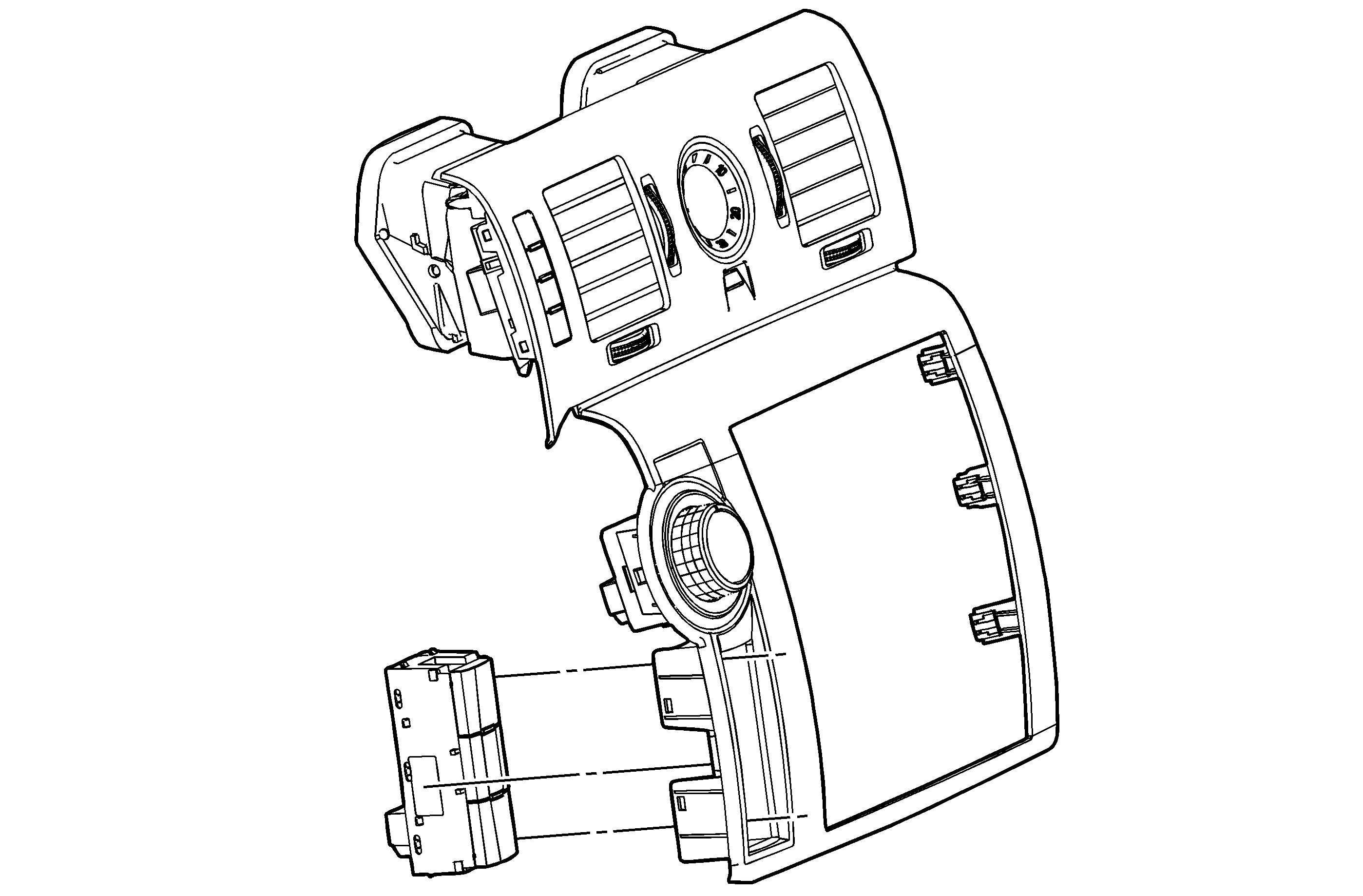
Circuit/System Description
Tow/haul mode enables the operator to achieve enhanced shift performance when towing or hauling a load. When tow/haul mode is selected, the tow/haul switch input signal to the body control module (BCM) is momentarily toggled to zero volts. This
signals the control solenoid (w/body and TCM) valve assembly to extend the length of time between upshifts and elevate transmission line pressure. Cycling the tow/haul switch again disables tow/haul mode and returns the transmission to a normal shift pattern.
The tow/haul switch is a momentary switch and is normally open. The internal spring in the switch will always cause the switch state to return to open when not held in to the closed position.
Diagnostic Aids
If the electrical circuit checks are OK and the tow/haul shift pattern is not occurring, there may be a mechanical/hydraulic condition that prevents tow/haul operation. Refer to
Symptoms - Automatic Transmission .
Reference Information
Schematic Reference
Automatic Transmission Controls Schematics
Connector End View Reference
Component Connector End Views
Electrical Information Reference
Scan Tool Reference
Control Module References for scan tool information
Circuit/System Verification
With a scan tool observe the Tow/Haul switch parameter in Body Controls data list. With the ignition On or engine running, operate the Tow/Haul switch several times, and observe the parameter as you operate the switch. The parameter should toggle between
Active and Inactive when the switch is operated.
Circuit/System Testing
- Ignition Off, transmission in Park, disconnect the Tow/Haul switch connector.
- Test for less than 1 Ohm of resistance between the Tow/Haul switch signal circuit terminal 12 and ground.
| ⇒ | If greater than the specified range, test the ground circuit for an Open/High resistance. |
- Ignition On, verify the scan tool Tow/Haul parameter displays Inactive.
| ⇒ | If not the specified value, test the signal circuit for a short to ground. If the circuit tests normal, replace the BCM. |
- Install a fused jumper between the signal circuit and ground. Verify the scan tool parameter displays Active.
| ⇒ | If not the specified value, test the signal circuit for a short to voltage or an open/high resistance. If the circuit tests normal, replace the BCM. |
- If all circuits test normal, replace the Tow/Haul switch.
Component Testing
- Ignition Off, transmission in Park, disconnect the Tow/Haul switch assembly.
- Test for infinite resistance between the Tow/Haul switch with the switch in the Open position.
| ⇒ | If not the specified value, replace the Tow/Haul switch assembly. |
- Depress and hold the Tow/Haul switch.
- Test for less than 1 Ohm of resistance between the Tow/Haul switch signal circuit terminals 12 and 10 while the switch is depressed.
| ⇒ | If greater than the specified value, replace the Tow/Haul switch assembly. |
Repair Instructions
Perform the
Diagnostic Repair Verification after completing the diagnostic procedure.
| • | Body Control Module (BCM) assembly replacement. Refer to
Control Module References for replacement, setup, and programming. |

