For 1990-2009 cars only
Special Tools
| • | J 43631 Ball Joint Remover |
| • | J 45851 Ball Joint Separator Protector Adaptors |
Removal Procedure
- Raise and support the vehicle. Refer to Lifting and Jacking the Vehicle.
- Remove the tire and wheel. Refer to Tire and Wheel Removal and Installation.
- Remove the stabilizer shaft links from the lower control arm. Refer to Stabilizer Shaft Link Replacement.
- Remove the wheel drive shaft. Refer to Wheel Drive Shaft Replacement.
- Remove the shock absorber lower nut and the bolt. Refer to Shock Absorber Replacement.
- Remove the torsion bars. Refer to Torsion Bar and Support Assembly Replacement.
- Remove the lower ball joint stud nut. Discard the nut.
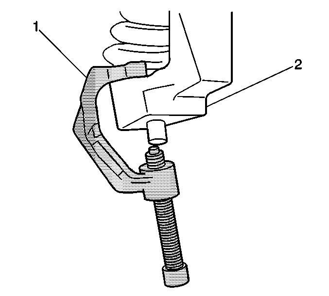
- Using the J 43631 (1) and the J 45851 , remove the lower ball joint stud from the steering knuckle.
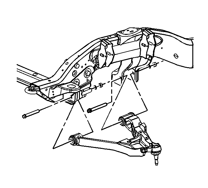
- Remove the lower control arm nuts and the washers.
- Remove the lower control arm bolts. Discard the bolts.

Important: DO NOT re-use the lower ball joint nut. Discard the nut and replace with NEW.

Installation Procedure
- Install the lower control arm.
- Install NEW lower control arm bolts.
- Install the washers with the shoulder facing the arm.
- Install the lower control arm retaining nuts.
- Install the lower ball joint stud to the steering knuckle.
- Install the NEW lower ball joint nut.
- If unable to use a torque angle meter, perform the following.
- Install the torsion bars. Refer to Torsion Bar and Support Assembly Replacement.
- Install the shock absorber lower nut and bolt. Refer to Shock Absorber Replacement.
- Install the wheel drive shaft. Refer to Wheel Drive Shaft Replacement.
- Install the stabilizer shaft links to the lower control arm. Refer to Stabilizer Shaft Link Replacement.
- Install the tire and wheel. Refer to Tire and Wheel Removal and Installation.
- Lower the vehicle.
- Verify the wheel alignment. Refer to Wheel Alignment Specifications.


Notice: Refer to Fastener Notice in the Preface section.
Tighten
Tighten the nuts to 215 N·m (160 lb ft).
Tighten
Tighten the nut to 50 N·m (37 lb ft) plus 120°.
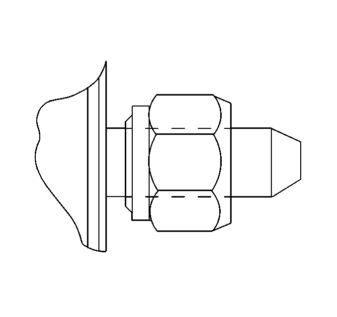
| • | After torquing the lower ball joint nut to the specifications, mark a reference point on the nut and the steering knuckle. |
| • | Rotate the lower ball joint two flats of the nut. This will equal the additional 120°. |
