Removal Procedure
Caution: Refer to Brake Fluid Irritant Caution in the Preface section.
Notice: Refer to Brake Fluid Effects on Paint and Electrical Components Notice in the Preface section.
- Apply and release the brake pedal 20 times to deplete the hydraulic brake booster accumulator reserve.
- Remove the 2 rear brake pipes (1) from the brake master cylinder.
- Remove the 2 front brake pipes (1) from the brake master cylinder.
- Disconnect the electrical connectors at the brake pressure modulator valve (BPMV).
- Disconnect the brake fluid level sensor electrical connector.
- Remove the brake master cylinder pushrod retainer bolt (1).
- Remove the brake master cylinder pushrod retainer (1).
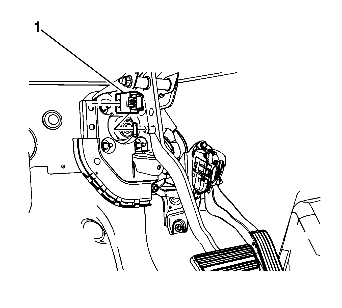
- Simultaneously remove the brake master cylinder pushrod and the stoplamp switch (1) from the brake pedal clevis pin.
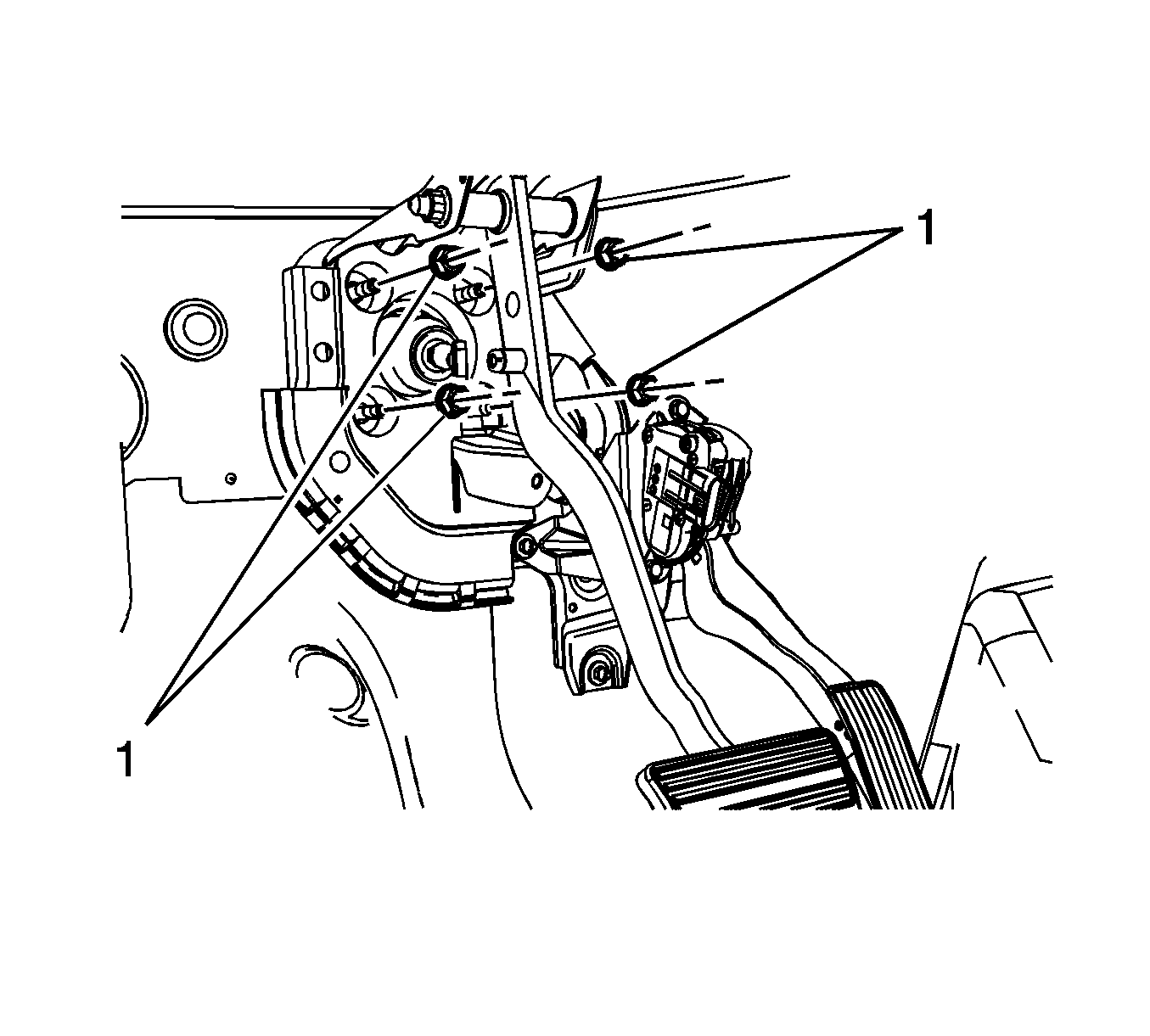
- Remove the brake master cylinder nuts (1).
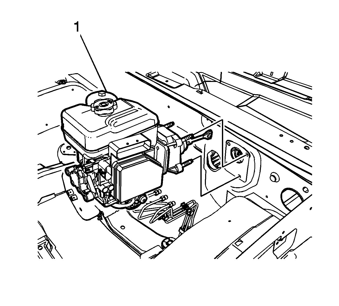
- Remove the brake master cylinder and power brake booster assembly (1).
Important: Reference mark the brake pipe location for correct installation.
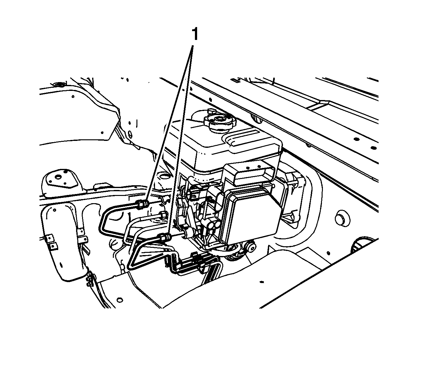
Cap the brake pipe fittings and plug the master cylinder outlet ports to prevent brake fluid loss and contamination.
Important: Reference mark the brake pipe location for correct installation.
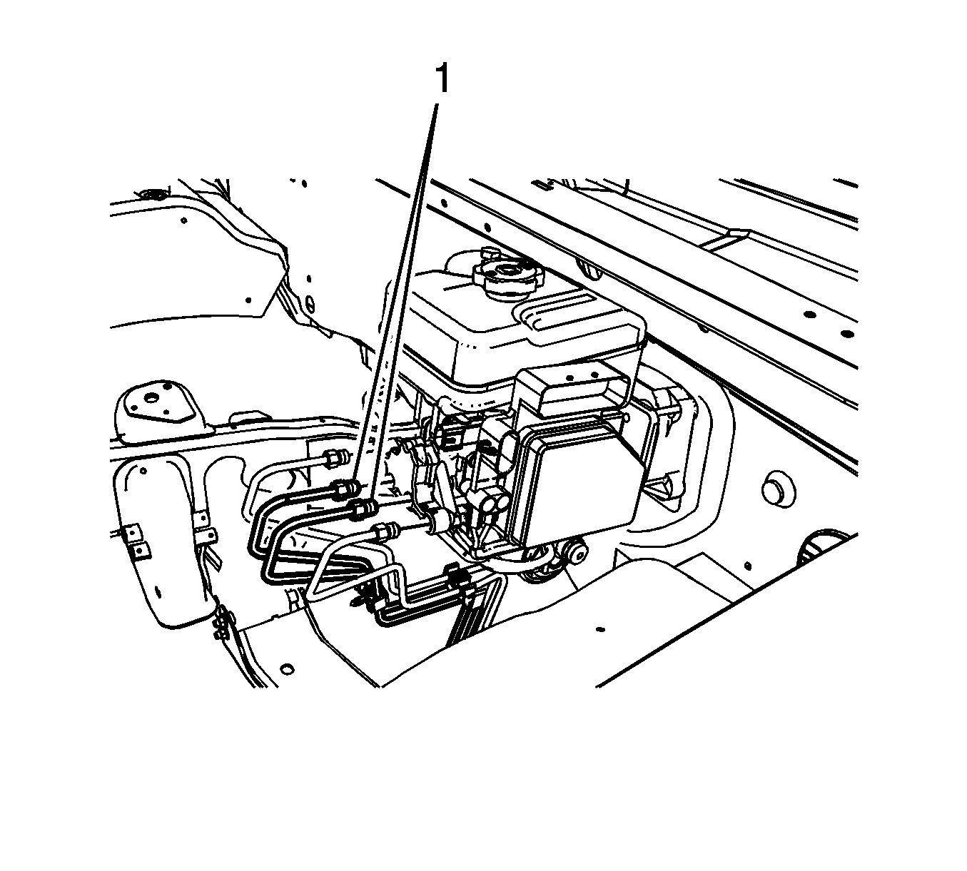
Cap the brake pipe fittings and plug the master cylinder outlet ports to prevent brake fluid loss and contamination.
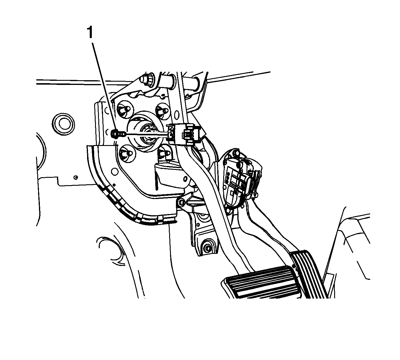
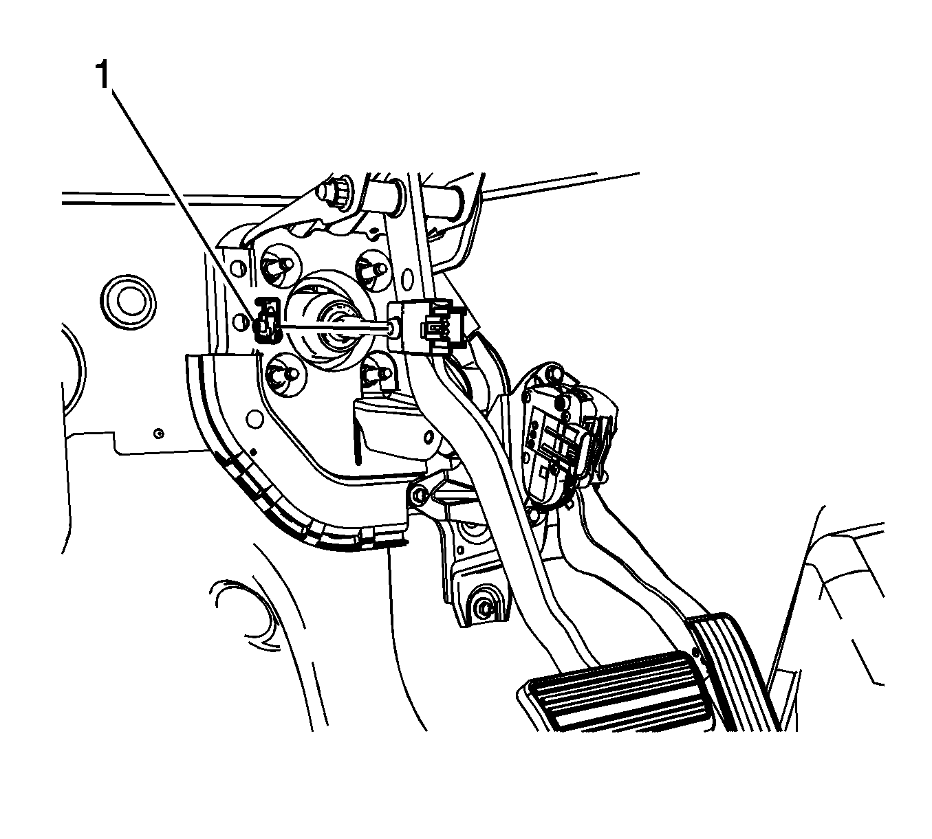
Important: It may be necessary to reposition or remove some of the wiring harnesses from their retainers to provide clearance to remove the brake master cylinder nuts.
Installation Procedure
- Install the brake master cylinder and power brake booster assembly (1).
- Install the brake master cylinder nuts (1).
- Position the wiring harnesses to the retainers, if removed.
- Simultaneously install the brake master cylinder pushrod and the stoplamp switch (1) to the brake pedal clevis pin.
- Install the brake master cylinder pushrod retainer (1).
- Install the brake master cylinder pushrod retainer bolt (1).
- Install the 2 front brake pipes (1) to the brake master cylinder.
- Connect the electrical connectors at the brake pressure modulator valve (BPMV).
- Connect the brake fluid level sensor electrical connector.
- Install the 2 rear brake pipes (1) to the brake master cylinder.
- Bleed the hydraulic brake system. Refer to Hydraulic Brake System Bleeding .

Notice: Refer to Fastener Notice in the Preface section.

Tighten
Tighten the nuts to 36 N·m (27 lb ft).


Tighten
Tighten the bolt to 10 N·m (89 lb in).

Tighten
Tighten the fittings to 25 N·m (18 lb ft).

Tighten
Tighten the fittings to 25 N·m (18 lb ft).
