For 1990-2009 cars only
Rear Compartment Side Trim Replacement - Right Side SUT
Removal Procedure
- Open the spare tire carrier to the full open position.
- Open the endgate.
- Remove the right rear sail panel molding. Refer to Sail Panel Molding Replacement .
- Open the midgate.
- Release the exterior midgate weatherstrip up to the stationary opera quarter window.
- Remove the bolts securing the rear floor cargo liner tie down loops to the body.
- Remove the bolts, loops and floor liner from the vehicle.
- Unlock and open the jack stowage lid.
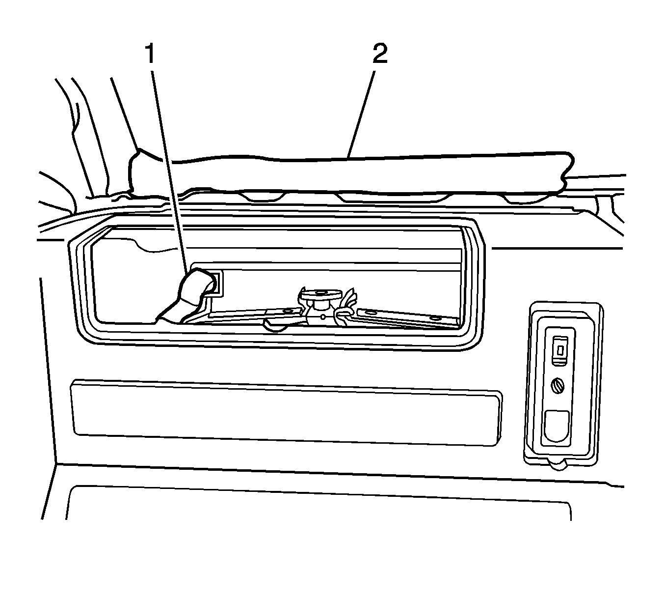
- Release the hook and loop attachment (1) for the jack handles (2) at the front of the jack stowage box.
- Remove the jack handles.
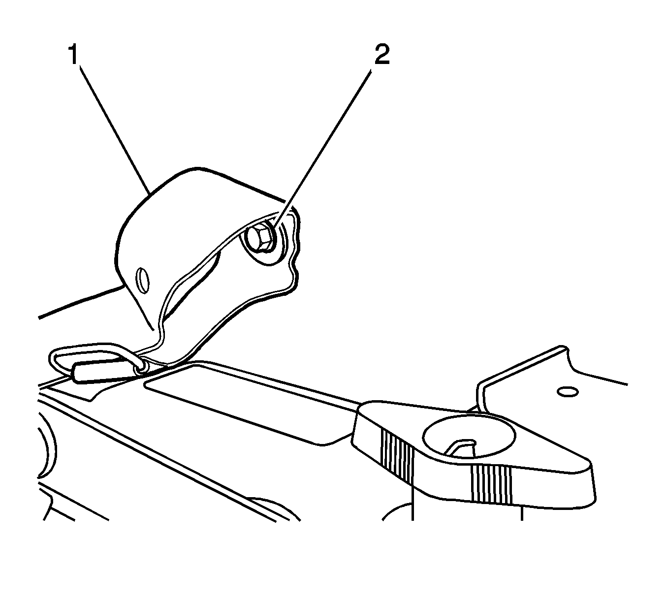
- Remove the bolts (2) securing the hook and loop attachment at the rear of the jack stowage box.
- Remove the nut securing the wheel blocks to the jack plate.
- Remove the wheel blocks from the jack stowage compartment.
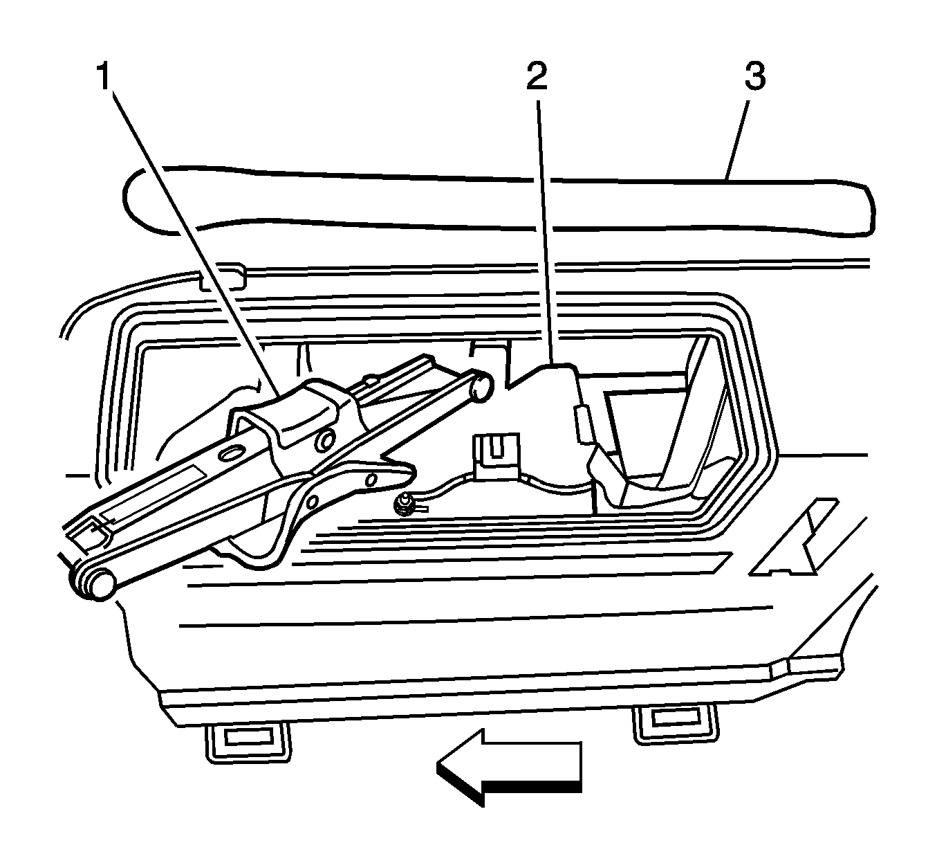
- Remove the nut securing the jack to the jack plate.
- Remove the jack (1).
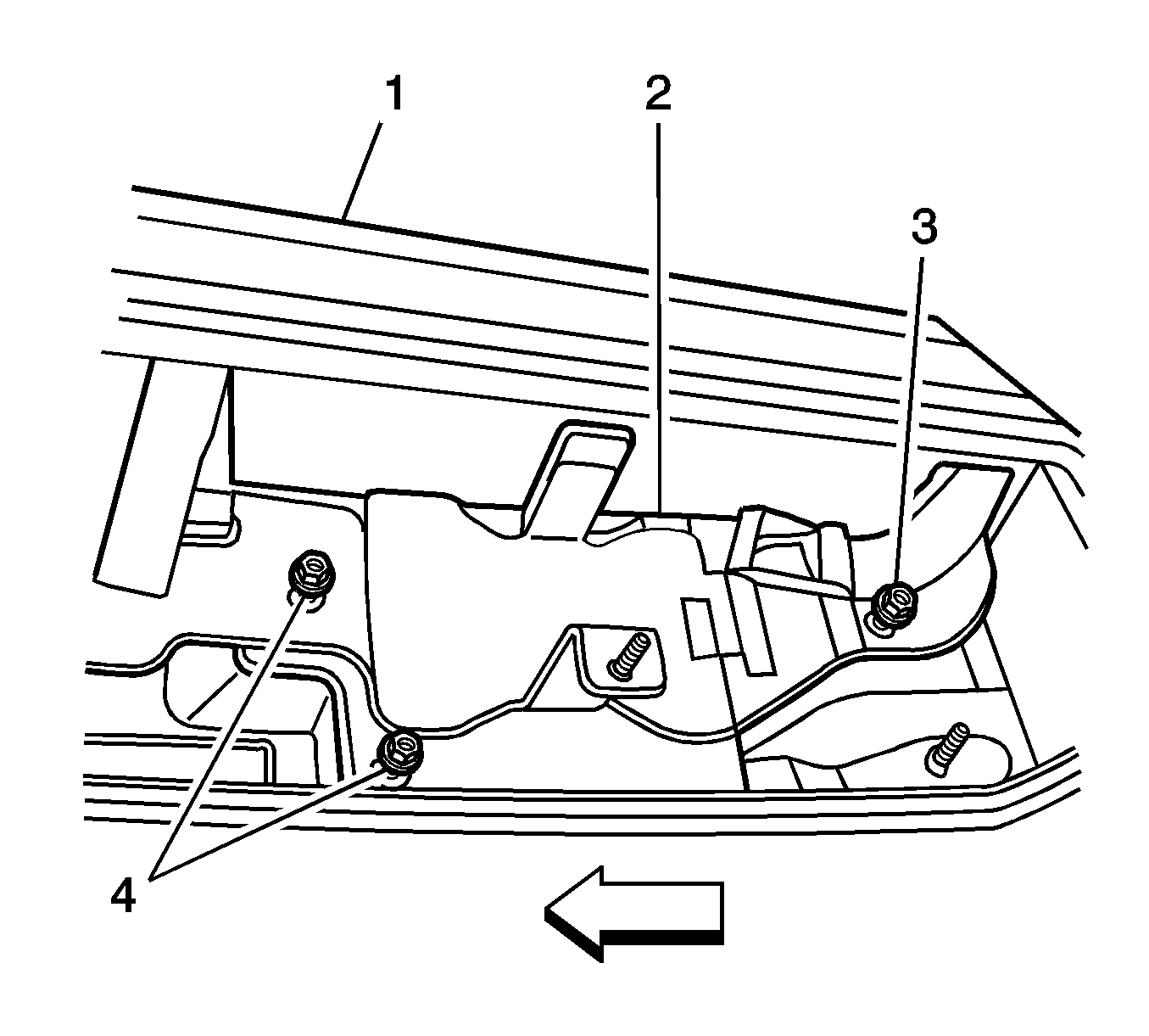
- Remove the nuts (3, 4) securing the jack plate (2) to the stowage box.
- Remove the jack plate (2).
- Remove the cap, nut and washer securing the inflator line to the rear accessory power outlet.
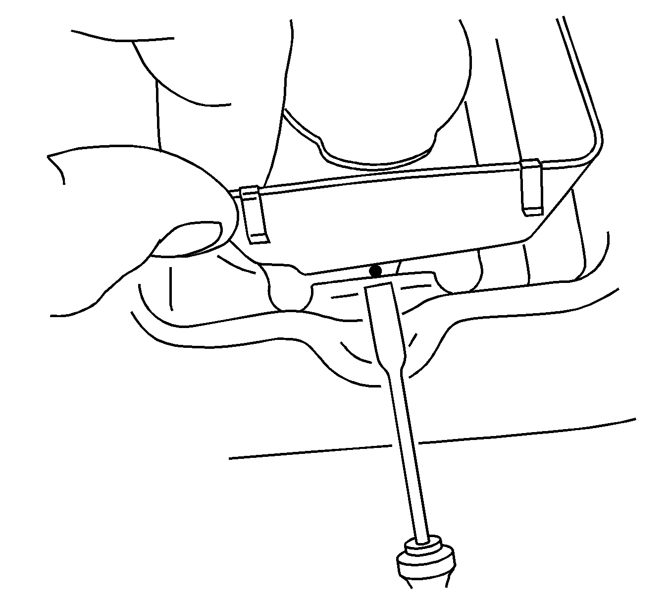
- With a flat-bladed tool, release the bottom edge of the accessory power outlet.
- Release the accessory power outlet from the right hand compartment side trim panel.
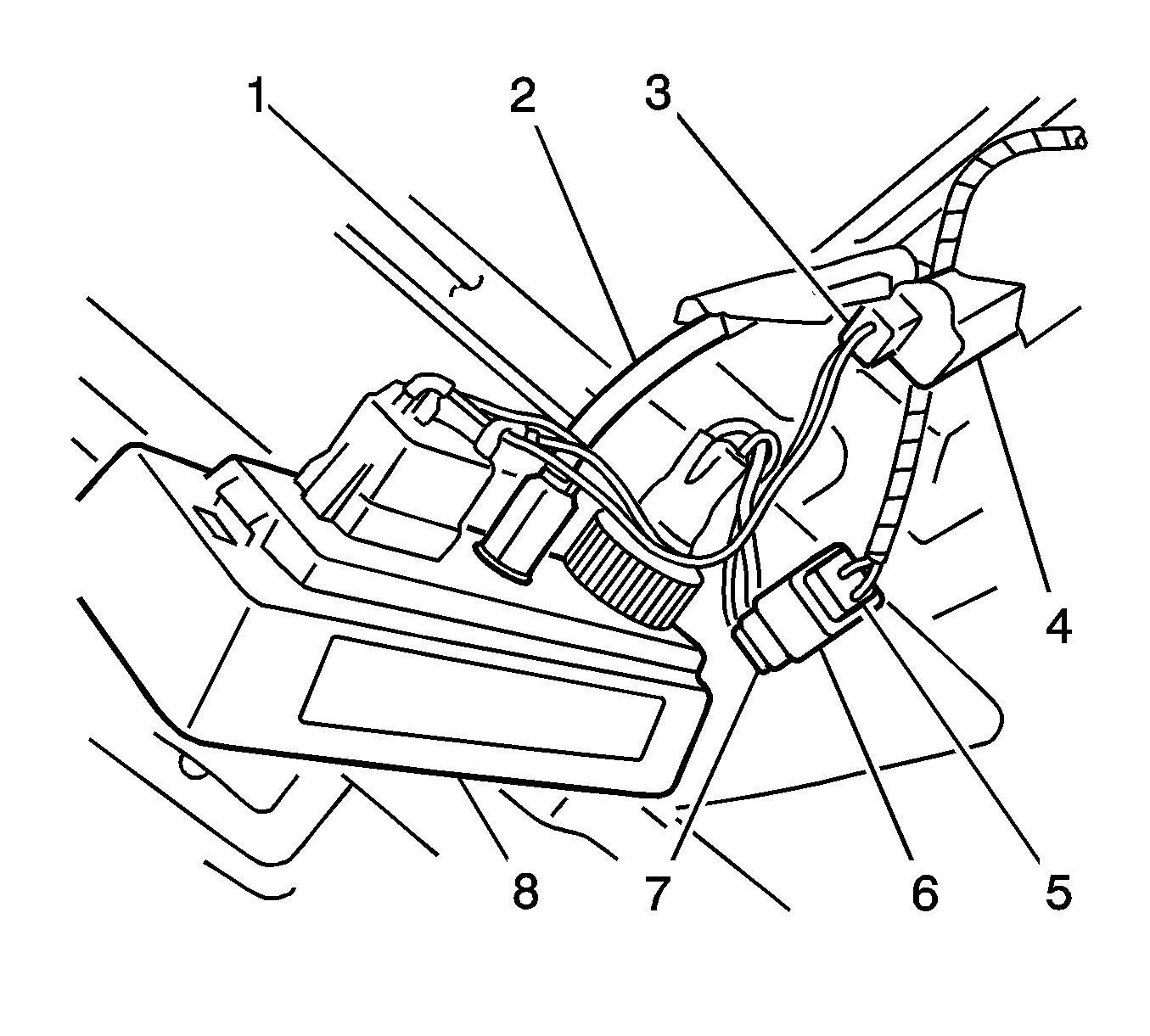
- Disconnect the inflator switch electrical connector (3).
- Remove the inflator line (2).
- Disconnect the electrical connector (7) for the 12-volt accessory outlet.
- Remove the accessory outlet panel (8) from the right hand compartment side trim panel.
- Remove the right hand rear compartment side trim panel from the pickup box.
Installation Procedure
- Position the right hand rear compartment side trim panel to the pickup box.
- Position the accessory outlet panel (8) to the right hand compartment side trim panel.
- Insert the inflator line into the accessory outlet box.
- Loosely install the washer and nut to the inflator line.
- Connect the electrical connectors to the inflator switch (4) and the 12-volt power outlet (5) electrical connectors.
- Position the right hand compartment side trim panel into vehicle position over the jack stowage plate studs.
- Install the jack plate (2) to the jack stowage box.
- Install the nuts (3, 4).
- Install the rear hook and loop and attachment bolt (2) to the rear inner compartment side panel.
- Install the front hook and loop and the attachment bolt (1) to the front inner compartment side panel.
- Install the jack (1) to the jack plate.
- Hand-tighten the nut to secure the jack to the jack plate.
- Install the wheel blocks to the jack plate.
- Hand-tighten the wheel blocks nut.
- Tighten the inflator line nut.
- Install the inflator line cap.
- Position the top side of the accessory outlet panel to the right hand compartment side panel.
- Push inward at the bottom edge in order to secure.
- Close the accessory outlet lid.
- Secure the jack handles (3) to the hook and loop attachment straps.
- Close the jack stowage lid and secure the lock.
- Install the rear floor cargo liner.
- Install the rear floor cargo liner tie down loops.
- Install the bolts.
- Reposition the midgate weatherstrip onto the pinch-weld flange over the front edge of the floor liner and front edge of the right side compartment trim panel.
- Close the midgate.
- Install the right rear sail panel molding. Refer to Sail Panel Molding Replacement .
- Close the endgate.
- Latch and secure the spare tire carrier.


Notice: Refer to Fastener Notice in the Preface section.
Tighten
Tighten the nuts to 50 N·m (37 lb ft).

Tighten
Tighten the bolt to 10 N·m (89 lb in).

Tighten
Tighten the bolt to 10 N·m (89 lb in).

Tighten
Tighten the inflator line nut to 10 N·m (89 lb in).
Tighten
Tighten the bolts to 10 N·m (89 lb in).
