The Borg Warner (BW) model 4493/4494 NR4 transfer case is a 2-speed, full-time 4WD, transfer case. The transfer case has an external planetary type differential, which has 2 different sets of pinion gears. The planetary differential provides a 40/60 torque split front/rear full-time. This means the front and rear propeller shafts are constantly being driven for maximum traction in all conditions. A high/low planetary carrier assembly provides the high and low ranges, which is a 6-pinion gear, sun gear, and annulus gear arrangement, giving a 2.64 low range reduction ratio in the BW 4493 and a 4:1 ratio in the BW 4494.
The BW 4493/4494 case halves are high-pressure die-cast magnesium. Ball bearings support the input shaft, the mainshaft, the front output shaft, and the rear output shaft. A needle roller bearing is located inside of the input shaft gear to support the front of the mainshaft. The rear of the mainshaft is supported by a bronze bearing inside the rear output shaft. The transfer case requires DEXRON®VI Automatic Transmission Fluid (ATF) GM P/N 88861003 (Canadian P/N 88861004), which is red in color. An oil pump pumps the fluid through the mainshaft oil gallery to the gears and bearings.
Transfer Case Shift Control Switch
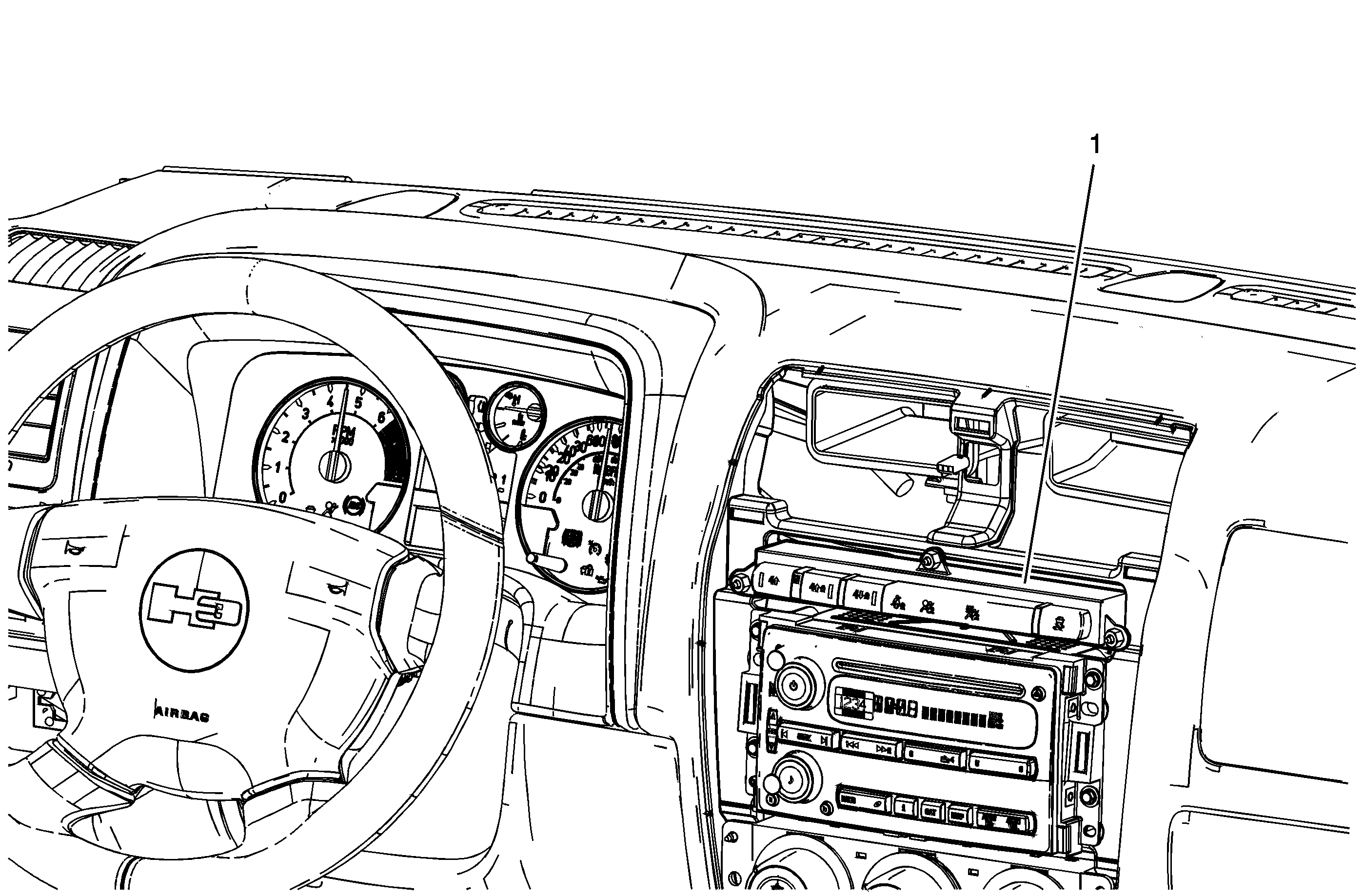
The BW 4493/4494 transfer case features a 4-button shift control switch (1) located on the instrument panel. When the vehicle has the ignition key in the RUN position, the transfer case shift control module starts monitoring the transfer case shift control switch to determine if the driver desires a new mode/gear position. At a single press of the transfer case shift control switch, the lamp of the new desired position begins flashing to inform the driver that the transfer case shift control module has received the request for a new mode/gear position. The lamp continues to flash until all shifting criteria have been met and the new mode/gear position has been reached, or has been engaged. Once the new mode/gear position is fully active, the switch indicator lamp for the new position remains ON constantly.
During normal driving situations, the transfer case operates in the 4HI mode. When the 4HI mode is selected, the transfer case shift control module sends 12-volts to an electrical motor, which is the transfer case encoder motor. This motor rotates the transfer case shift detent lever shaft which moves the shift forks and range sleeve to obtain different modes/ranges.
The BW 4493/4494 transfer case has the added feature of also providing the driver with 3 manual mode/range positions:
| • | 4HI - 4-Wheel Drive High Open |
| • | 4HI Lock - 4-Wheel Drive High Locked |
| • | 4LO Lock - 4-Wheel Drive Low Locked |
The driver may choose to select any of these mode/range positions while driving the vehicle. However, the transfer case will not allow a shift into or out of 4LO Lock unless the following criteria has been met:
| • | The engine is running. |
| • | The automatic transmission is in NEUTRAL. |
| • | The vehicle speed is below 5 km/h (3 mph). |
This transfer case also has a NEUTRAL position. A shift to the NEUTRAL position allows the vehicle to be towed without the transmission output shaft rotating. Refer to the Owners Manual for instructions for proper towing of the vehicle.
NEUTRAL position may be obtained only if the following criteria have been met:
| • | The engine is running or the ignition is ON. |
| • | The automatic transmission is in NEUTRAL. |
| • | The vehicle speed is below 5 km/h (3 mph). |
| • | The transfer case is in the 4HI mode. |
Once these conditions have been met, press and hold both the 4HI and 4LO Lock buttons for 10 seconds. When the system completes the shift to NEUTRAL, the red NEUTRAL indicator illuminates.
The BW 4493/4494 transfer case has 1 other additional feature along with the 3 modes. The electronic rear differential lock can only be used in the 4LO Lock mode with a vehicle speed at or below 32 km/h (20 mph).
4HI Mode Power Flow
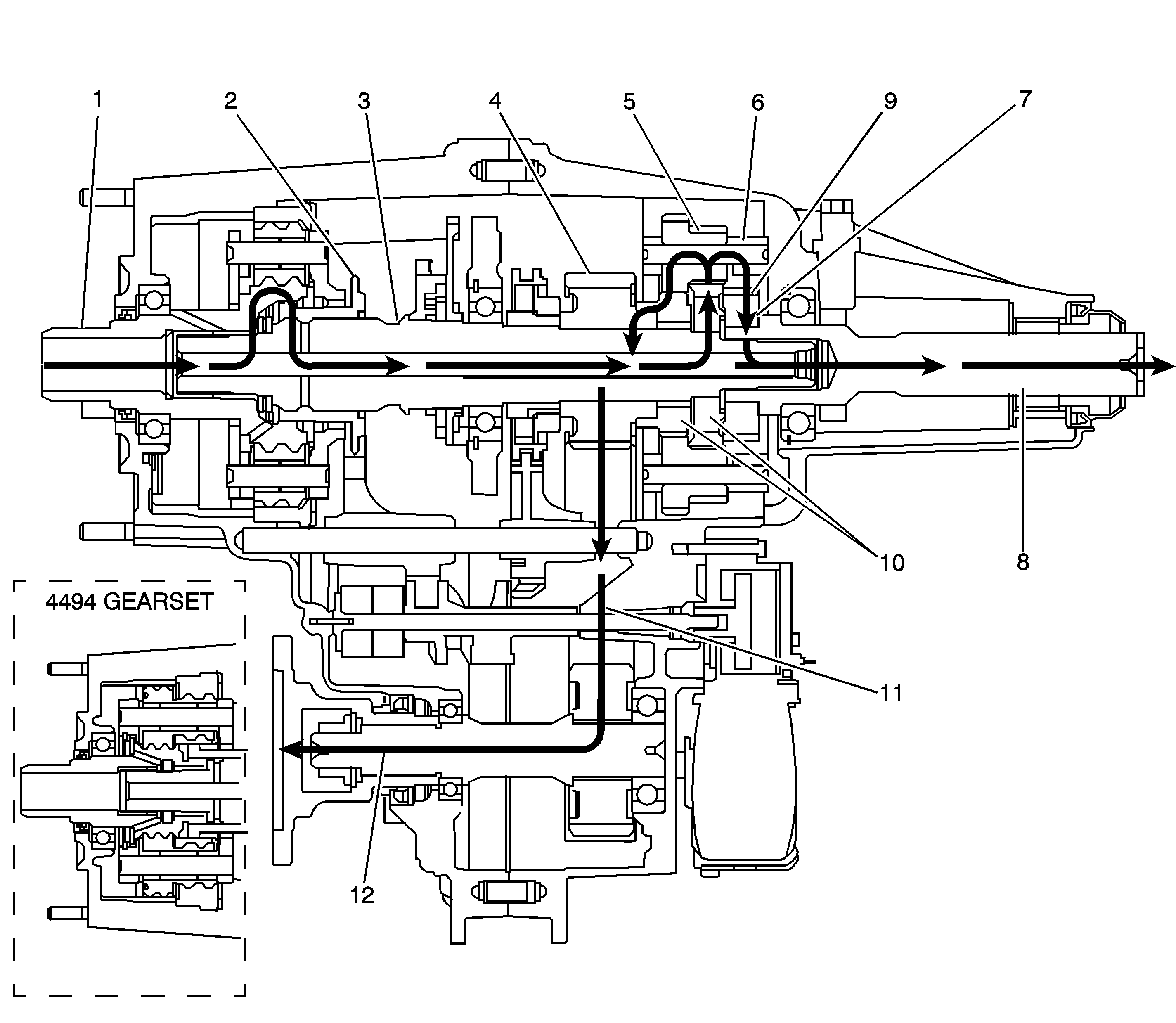
When the BW 4493, shown, or the BW 4494, shown in inset, is in 4HI mode, the engine power flows from the transmission to the input shaft (1). The input shaft (1) is connected to the mainshaft (3) by the high/low range sleeve (2). The high/low range sleeve (2) outer teeth are engaged with the input shaft (1) high-speed teeth. The range collar is slip splined to the mainshaft (3). The mainshaft (3) delivers the power flow to the planetary differential (6), which splits the torque 40 percent through the front differential pinion gears (5) to the front output sun gear (10). The torque to the front axle then goes through the drive sprocket (4), via the chain (11) to the front output shaft (12) and to the front axle. The differential planetary splits the torque 60 percent to differential rear pinion gears (9) and rear output sun gear (7). The rear output sun gear is connected to the rear output shaft (8) and the torque flows to the rear axle. In the 4HI mode, if traction is lost to 1 axle and the tires spin, the traction assist system (TAS) applies braking to the spinning tires and the engine power is delivered to the other tires.
4HI Lock Mode Power Flow
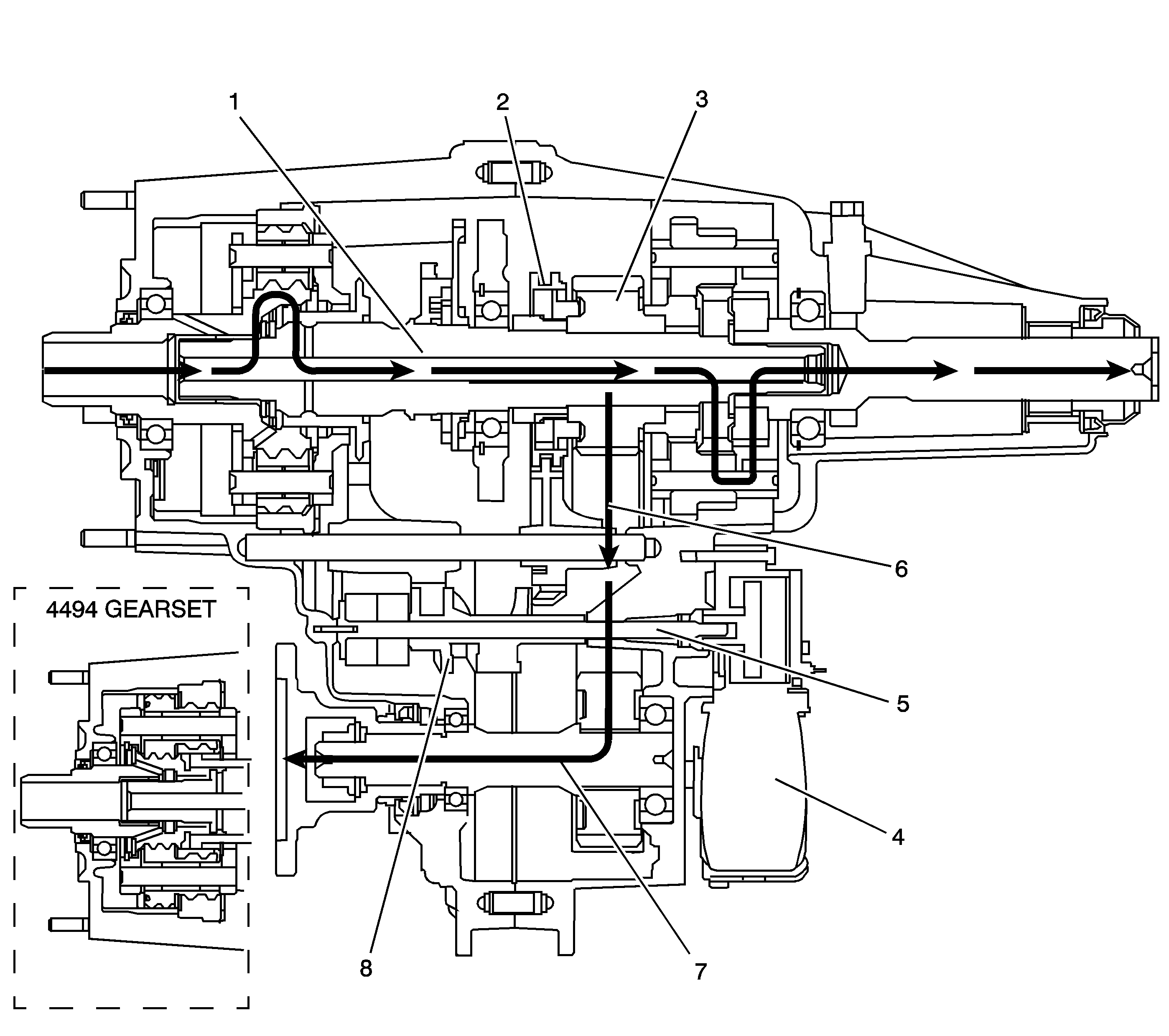
When the BW 4493, shown, or the BW 4494, shown in inset, shifts to the 4HI Lock mode, the encoder motor (4) turns the shift cam shaft (5), to rotate the shift cam (8). The action of the shift cam (8) moves the lockup mode shift fork rearward along with the lockup shift collar assembly (2). The lockup shift assembly sleeve (2) locks the mainshaft (1) to the drive sprocket (3). Torque is sent by the chain (6) to the front output shaft (7) and to the front axle. The torque distribution in this mode is now determined by vehicle dynamic conditions and weight distribution. The planetary differential is not operating, and both the front and rear propeller shafts are being driven at equal RPM, therefore giving a 4 high lock mode. This mode should only be used for extra traction during off road use. Using this mode on dry pavement causes tire scuffing.
4LO Lock Mode Power Flow
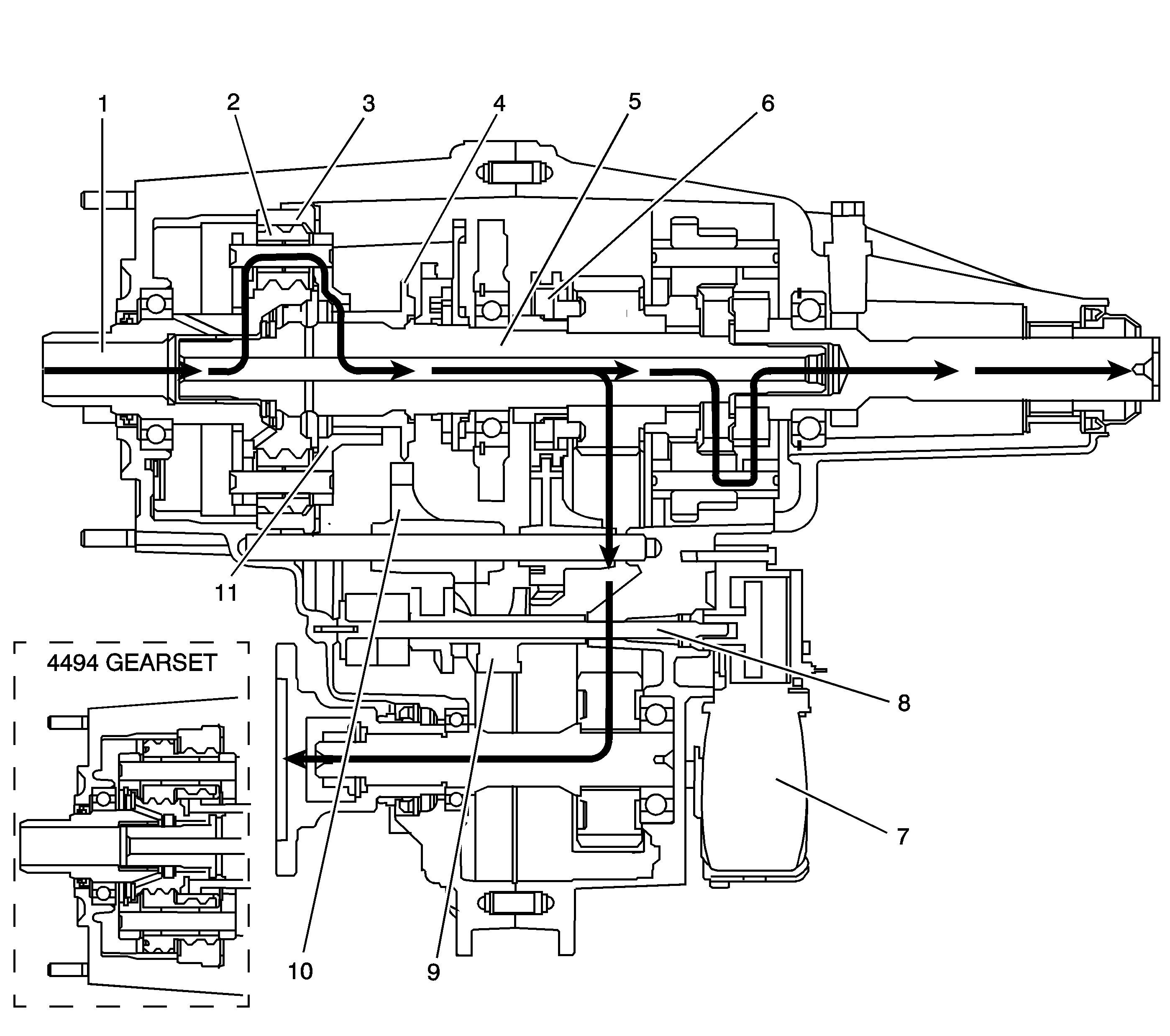
When the BW 4493, shown, or the BW 4494, shown in inset, shifts the transfer case to the 4LO Lock mode, it commands the encoder motor (7) to turn the shift cam shaft (8), to rotate the shift cam (9). The range cam profile on the shift cam (9) moves the high/range shift fork (10) and the high/low range sleeve (4) rearward to the 4LO Lock range position. The high/low range sleeve (4) outer teeth disengage from the input shaft (1) high-speed teeth. The high/low range sleeve (4) outer teeth then engage in the high/low planetary carrier teeth (11). The power flow is now from planetary teeth on the input shaft (1) to the planetary gears (2) in the carrier. Rotating the planetary gears, which are engaged in the ring gear (3), rotates the planetary carrier. The planetary carrier delivers the power to the high/low range sleeve (4). The high/low range sleeve (4) then drives the mainshaft (5), providing a 2.64:1 reduction to the speed of the mainshaft (5). When in the 4LO Lock position, the lockup mode shift fork and lockup shift assembly (6) engages in the same way as in the 4HI Lock mode.
NEUTRAL Mode Power Flow
When the BW 4493/4494 shifts to the NEUTRAL position, the high/low range sleeve is centered between the input shaft and the high/low planetary carrier. The high/low range sleeve is not engaged with either the input shaft or the high/low planetary carrier teeth. The planetary differential is in the AWD mode.
Transfer Case Electrical Components
View the list of major electrical components that make up the full-time 4 wheel drive transfer case (FT4WD) system below.
Service 4WD Message
The SERVICE 4WD message is displayed on the driver information center, which is an integral part of the cluster and cannot be serviced separately. This message is used to inform the driver of malfunctions within the FT4WD transfer case system. The SERVICE 4WD message is controlled by the transfer case shift control module via a Class 2 message.
Transfer Case Encoder
The encoder is mounted to the transfer case encoder motor assembly and is replaced only as an assembly. The encoder converts the shift detent lever shaft position, representing a mode/range into electrical signal inputs to the transfer case shift control module. The module detects what position the transfer case is in by monitoring the 4 encoder channels, P, B, A, and C. These inputs translate into 4HI, 4HI Lock, 4LO Lock, and NEUTRAL, or whether the motor is still in transition between gears.
The transfer case encoder channel circuits may be monitored using a scan tool.
Transfer Case Encoder Motor
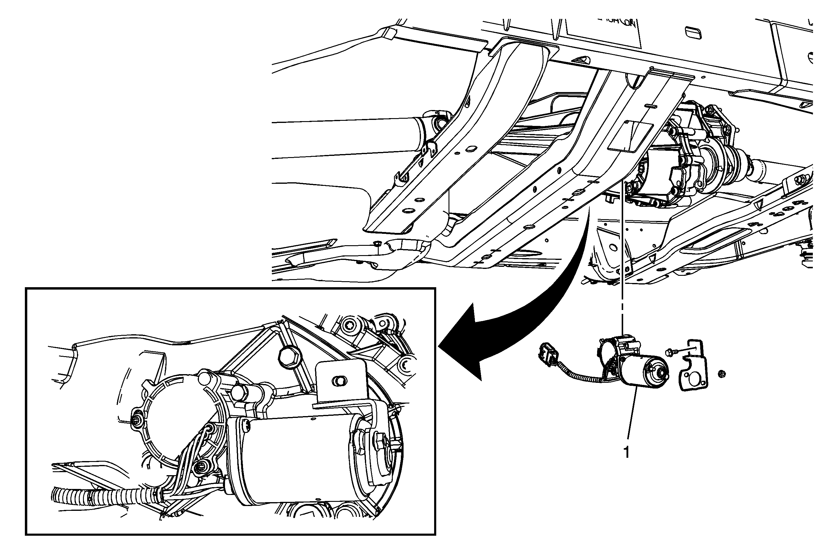
The transfer case encoder motor (1) consists of a permanent magnet DC motor and gear reduction assembly. It is located on the left hand side of the transfer case. When activated, it turns the shift detent lever shaft of the transfer case clockwise or counterclockwise, to shift the transfer case by moving the shift forks and collar assemblies inside the transfer case. The encoder motor is controlled through a 12-volt circuit provided by the transfer case shift control module. This circuit consists of a driver on both the Motor Control A and Motor Control B circuits. The encoder motor is bi-directional to allow the motor to shift the transfer case from 4HI or 4HI Lock to NEUTRAL and 4LO Lock positions.
Both the motor control drivers and motor control return drivers can be turned on using a scan tool. You may also monitor Motor Control A and B circuits using a scan tool.
Transfer Case Shift Control Module
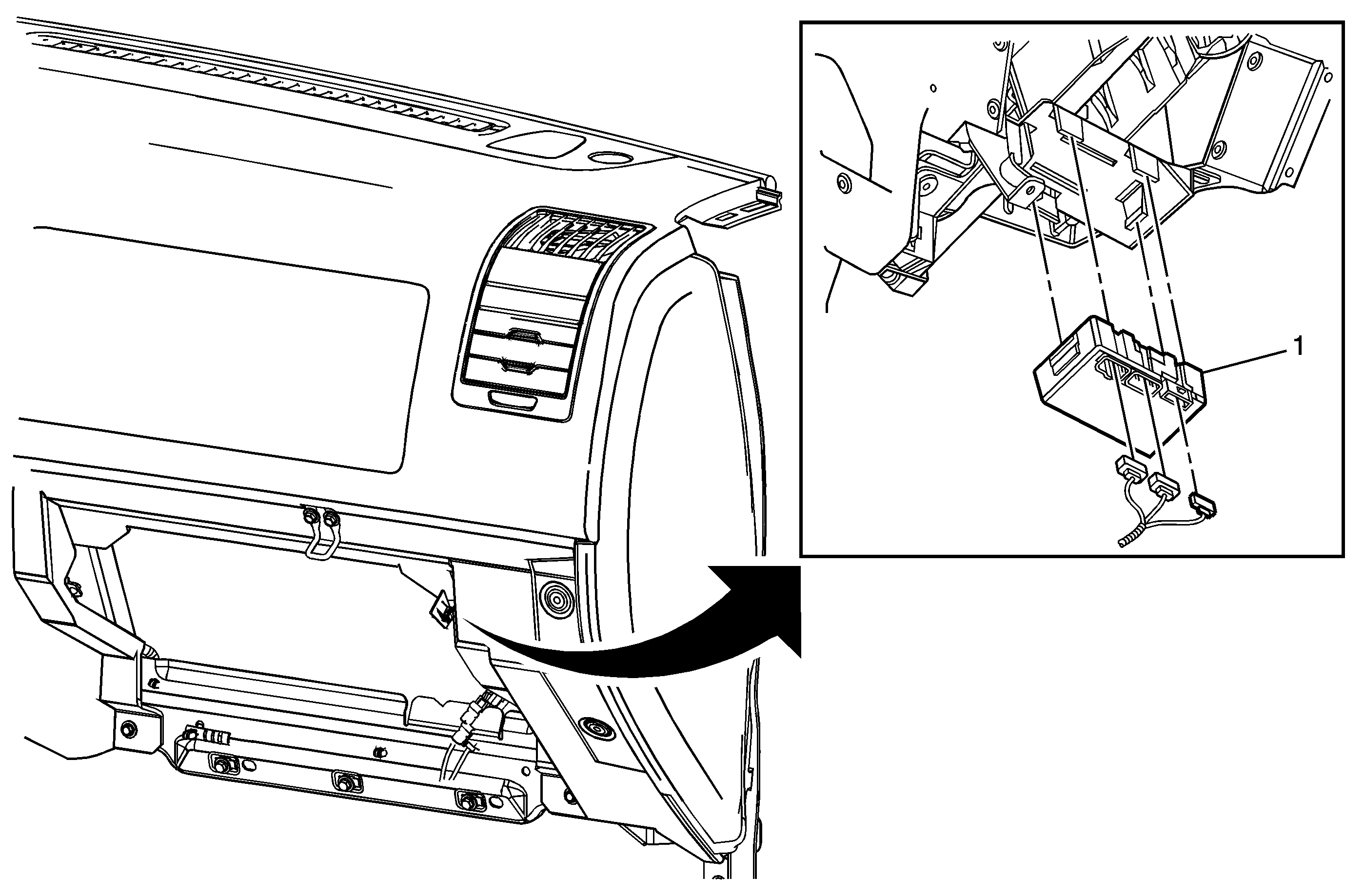
The transfer case shift control module (1) uses the VIN information for calculations that are required for the different calibrations used base on axle ratio, transmission, tire size, and engine. The system does not know which calibration to use without this information. This information is provided to the transfer case shift control module via Class 2 data bus from the powertrain control module (PCM). The transfer case shift control module monitors vehicle speed via the Class 2 data bus from the PCM as well as controlling the operation of the transfer case encoder motor assembly.
