GM Service Manual Online
For 1990-2009 cars only
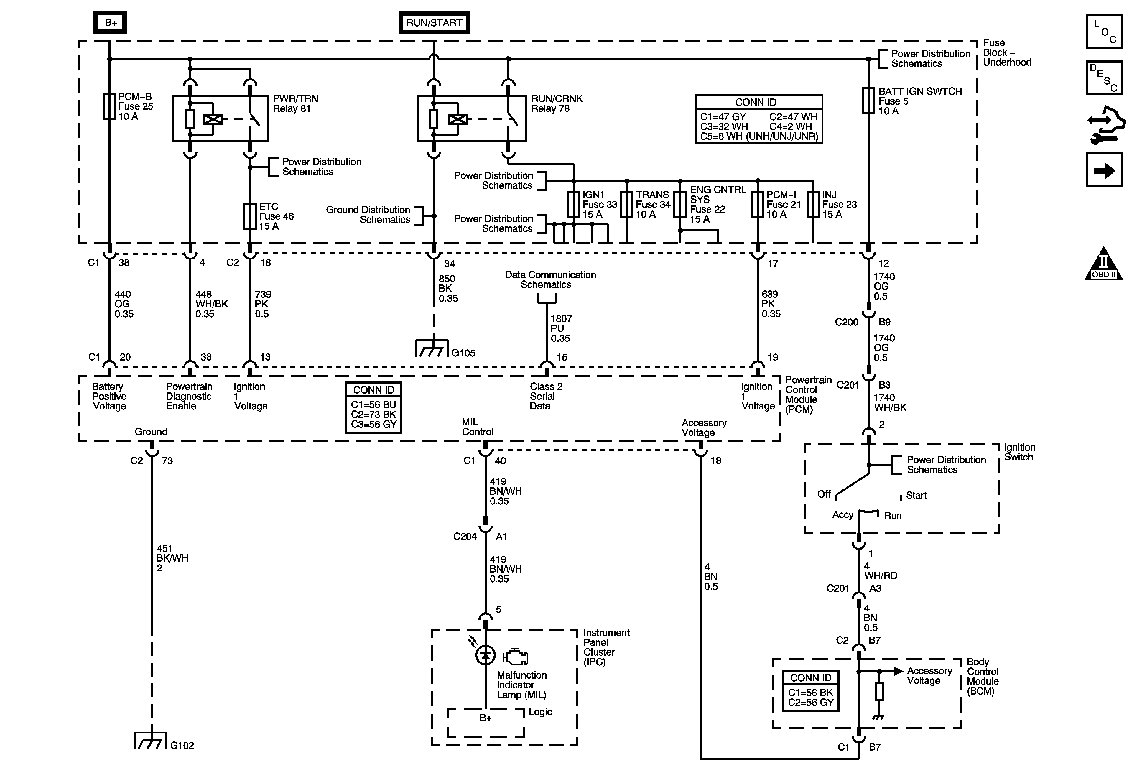
Figure 1:

Module Power, Ground, Serial Data, MIL, and DLC

Object Number: 1776824  Size: FS
Master Electrical Component List
Powertrain Control Module Description
Control Module References
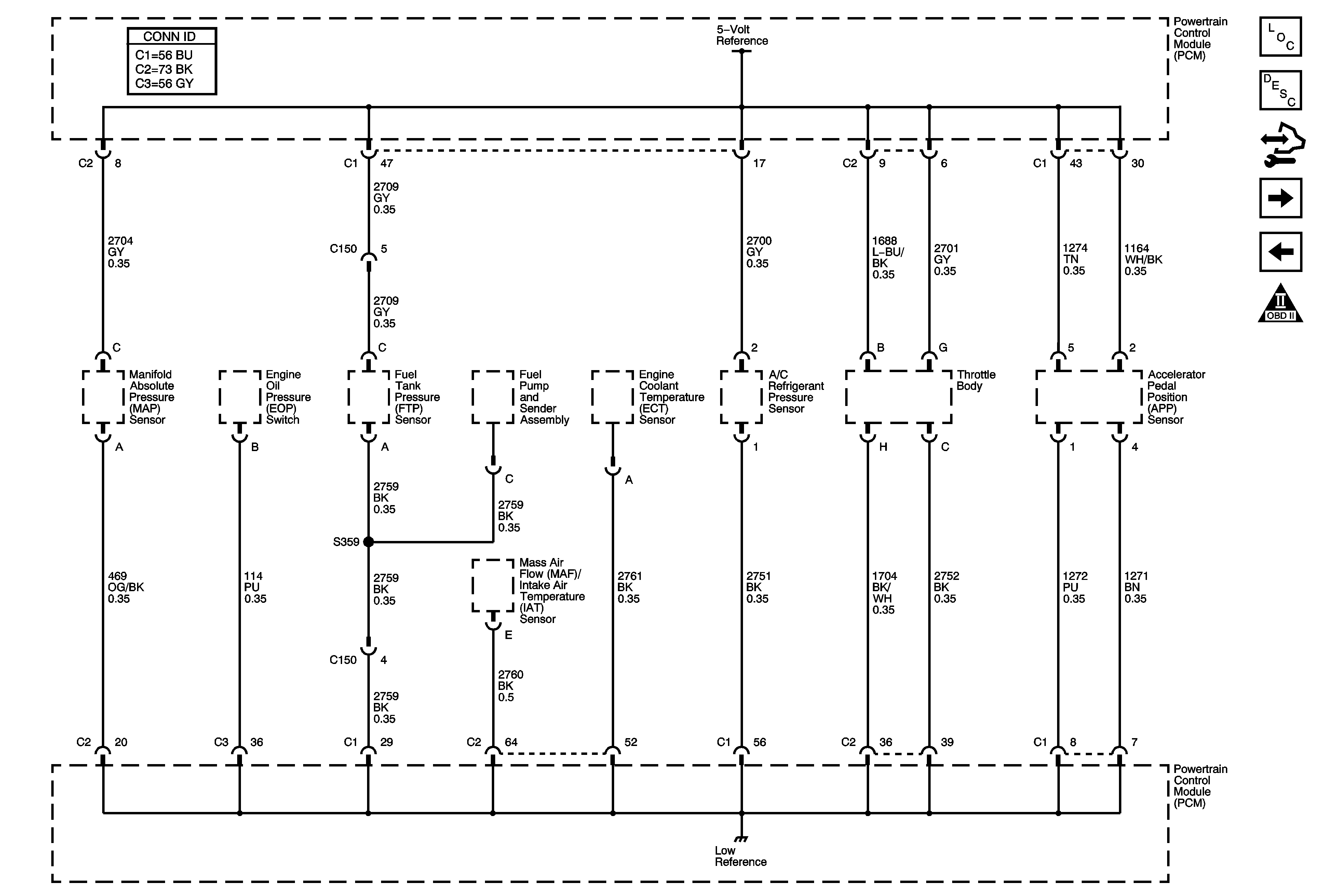
Engine Data Sensors - 5-Volt and Low Reference
Engine Controls Schematic Icons
B+ Bus - Underhood Fuse Block - 1 of 2
G105
B+ Bus - Underhood Fuse Block - 1 of 2
RUN/CRNK Relay Bus - 2 of 3, ABS/VSES, A/C CLUTCH, BCK/UP, and IGN1 Fuses
B+ Bus - Underhood Fuse Block - 1 of 2
Data Link Connector (DLC) Schematics
G105
Ignition Switch and BATT IGN SWTCH Fuse
G100, G102, G103, G104, G110, and G120
Figure 2:

Engine Data Sensors - 5-Volt and Low Reference


Object Number: 1776836  Size: FS
Master Electrical Component List
Powertrain Control Module Description
Control Module References
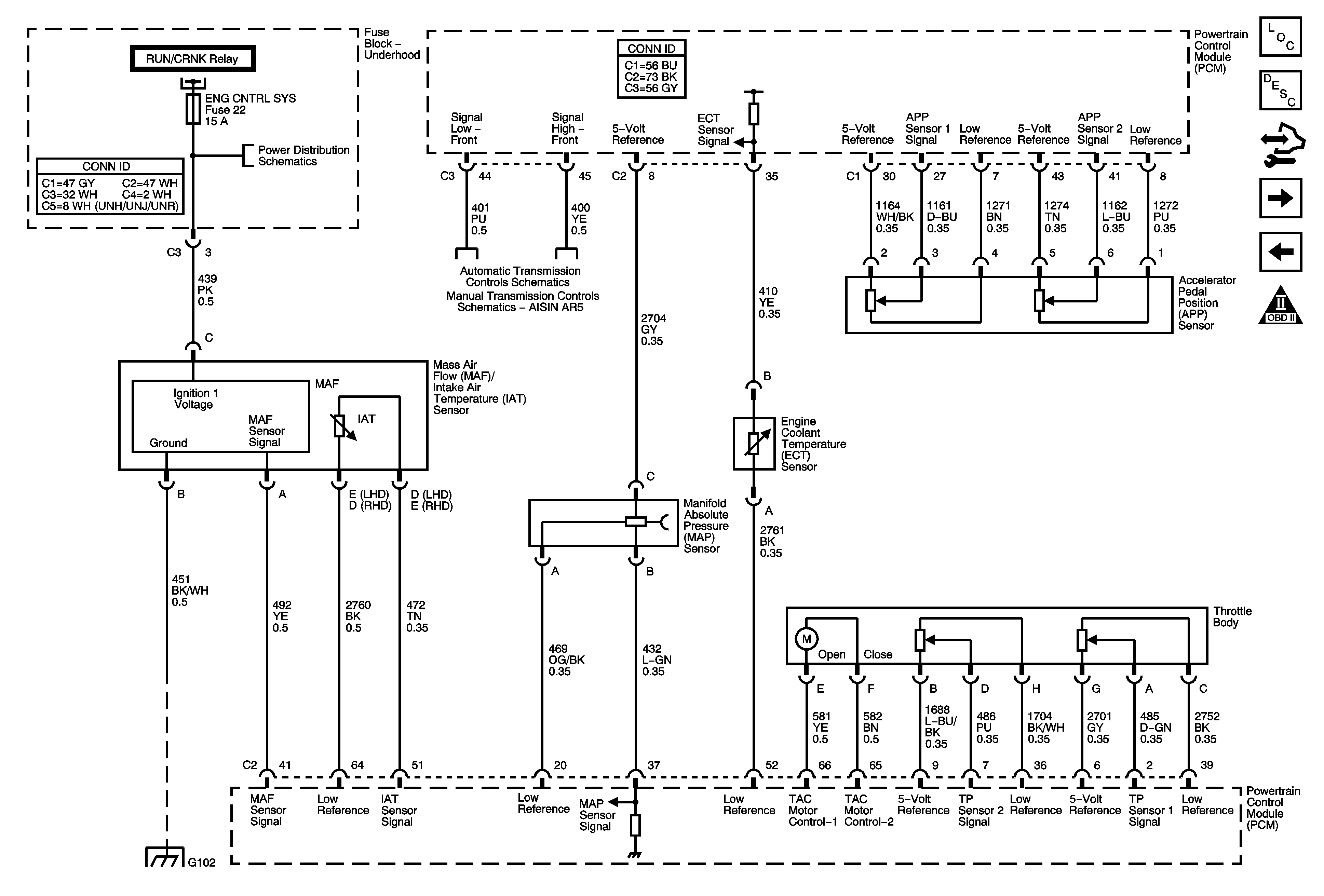
Engine Data Sensors - Pressure, Temperature, and Throttle Actuator Controls
Module Power, Ground, Serial Data, MIL, and DLC
Engine Controls Schematic Icons
Figure 3:

Engine Data Sensors - Pressure, Temperature, and Throttle Actuator Controls


Object Number: 1776855  Size: FS
Master Electrical Component List
Powertrain Control Module Description
Control Module References
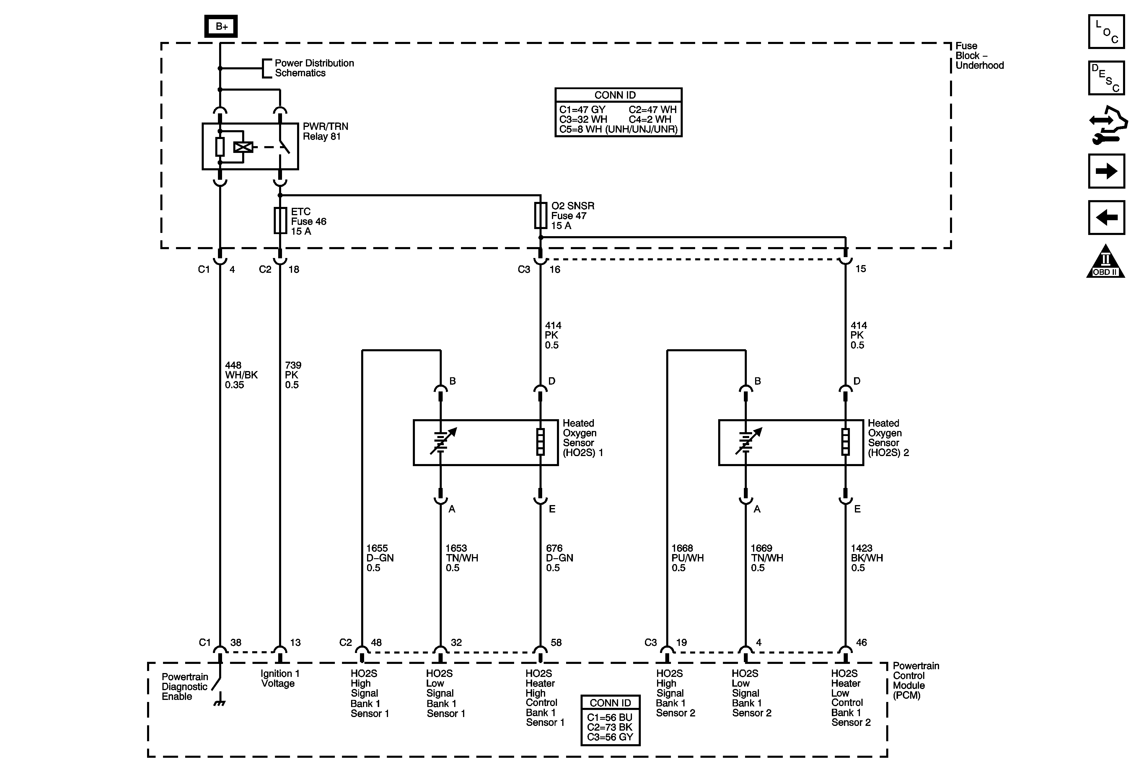
Engine Data Sensors - Oxygen Sensors
Engine Data Sensors - 5-Volt and Low Reference
Engine Controls Schematic Icons
RUN/CRNK Relay Bus - 3 of 3, ENG CNTRL SYS, INJ, and PCM-I Fuses
TCC Brake/Cruise Release Switch and Vehicle Speed Sensor
Manual Transmission Schematics
G100, G102, G103, G104, G110, and G120
Figure 4:

Engine Data Sensors - Oxygen Sensors


Object Number: 1776865  Size: FS
Master Electrical Component List
Powertrain Control Module Description
Control Module References
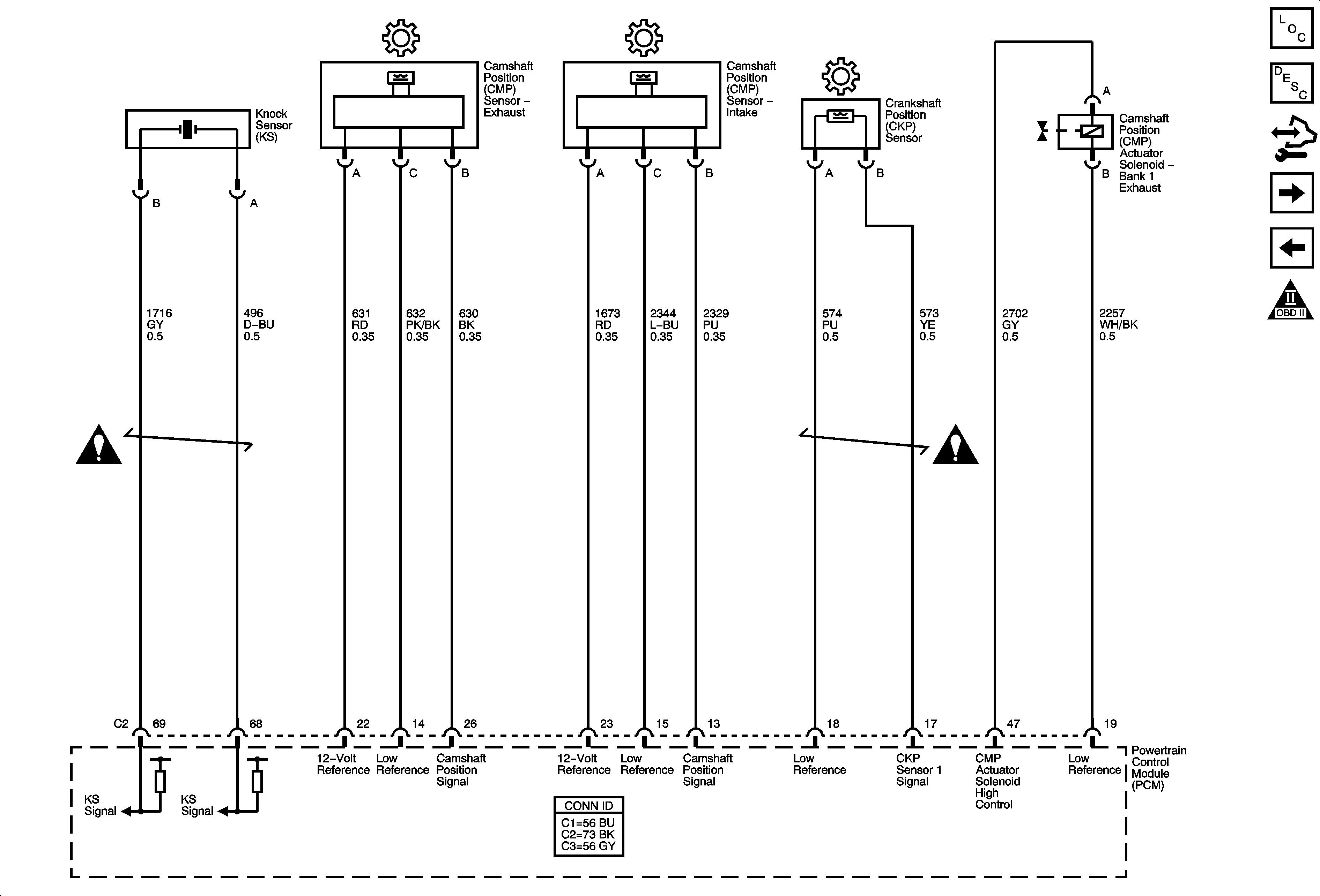
Ignition Controls - Sensors
Engine Data Sensors - Pressure, Temperature, and Throttle Actuator Controls
Engine Controls Schematic Icons
B+ Bus - Underhood Fuse Block - 1 of 2
Figure 5:

Ignition Controls - Sensors


Object Number: 1776880  Size: FS
Master Electrical Component List
Powertrain Control Module Description
Control Module References
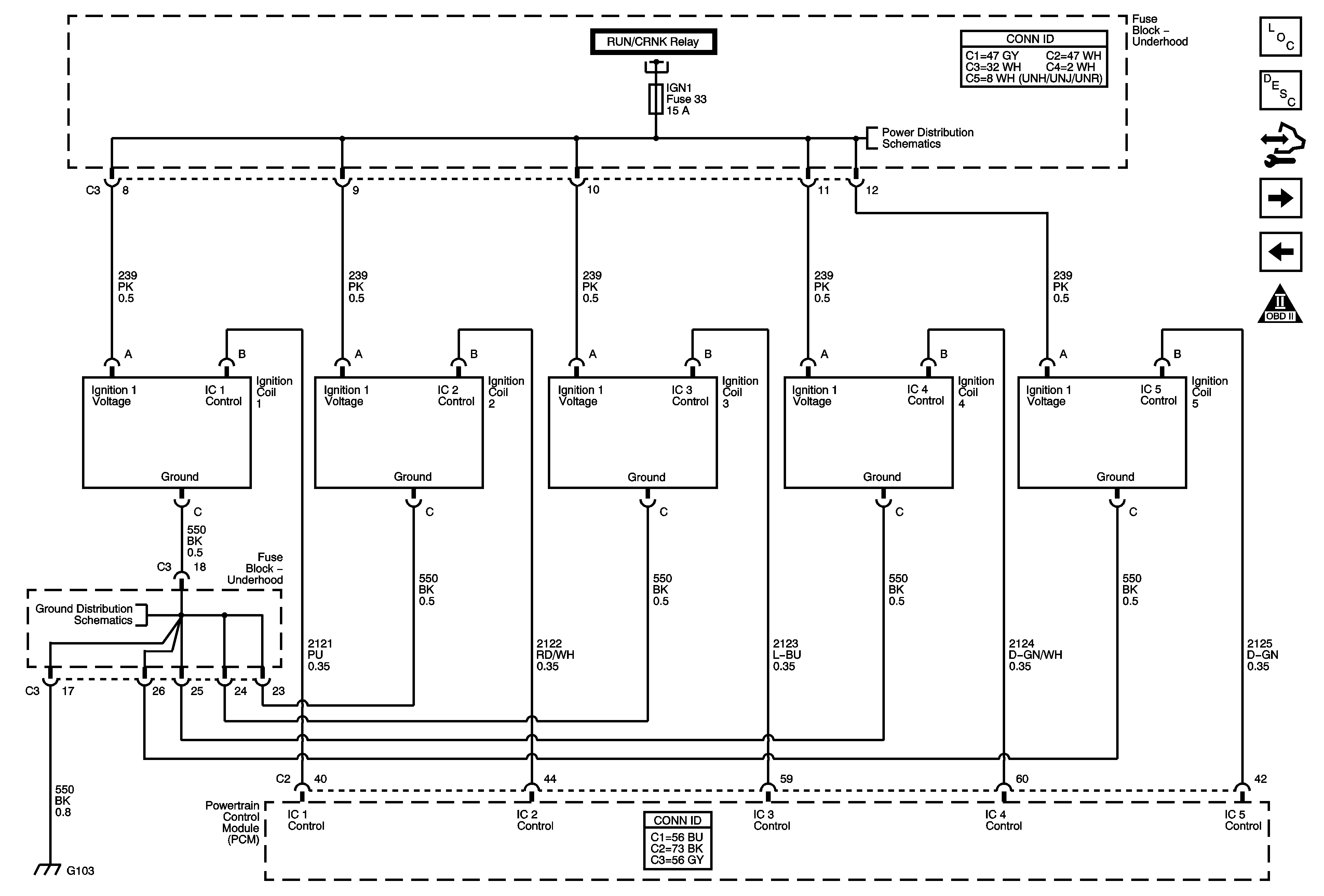
Ignition Controls - Ignition System
Engine Data Sensors - Oxygen Sensors
Engine Controls Schematic Icons
Figure 6:

Ignition Controls - Ignition System


Object Number: 1776888  Size: FS
Master Electrical Component List
Powertrain Control Module Description
Control Module References
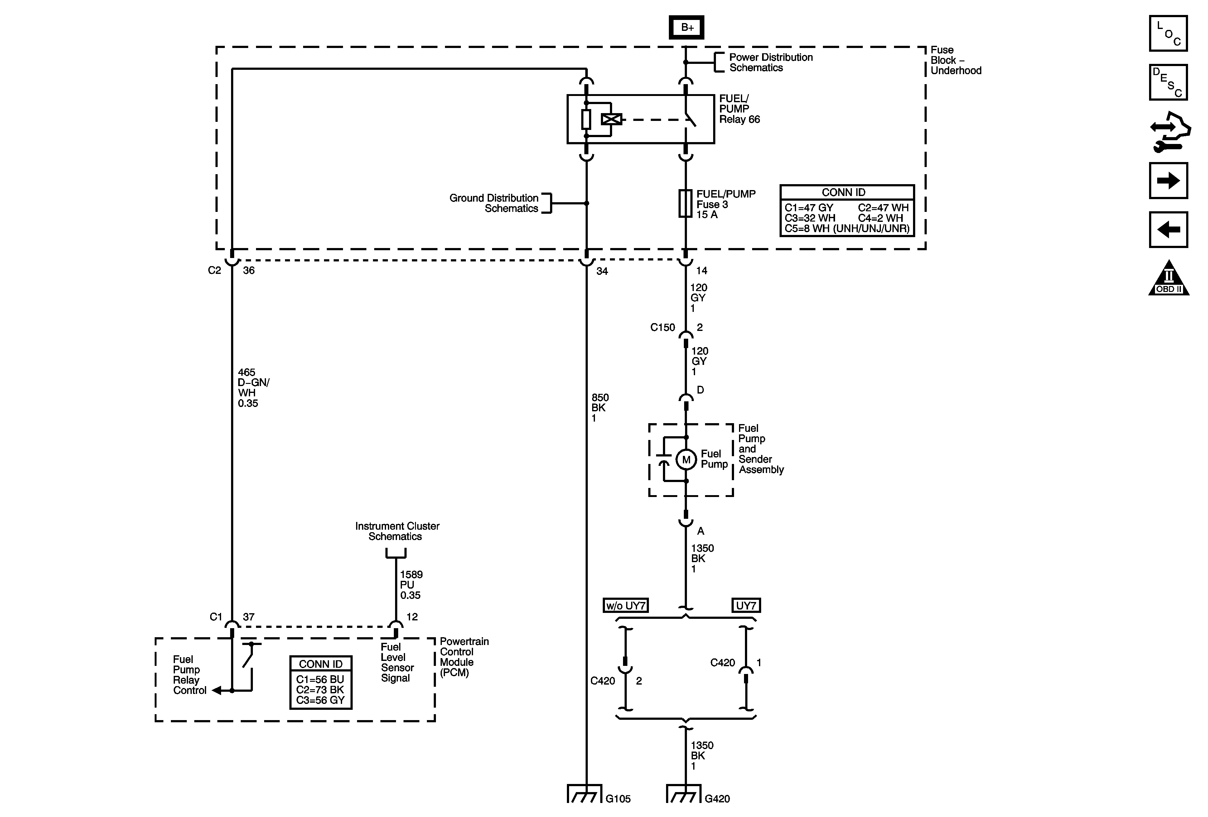
Fuel Controls
Ignition Controls - Sensors
Engine Controls Schematic Icons
Module Power, Ground, Serial Data, MIL, and DLC
RUN/CRNK Relay Bus - 2 of 3, ABS/VSES, A/C CLUTCH, BCK/UP, and IGN1 Fuses
G100, G102, G103, G104, G110, and G120
Figure 7:

Fuel Controls


Object Number: 1776899  Size: FS
Master Electrical Component List
Powertrain Control Module Description
Control Module References
Fuel Injection Controls
Ignition Controls - Ignition System
Engine Controls Schematic Icons
B+ Bus - Underhood Fuse Block - 2 of 2
G105
Gages
G105
G420
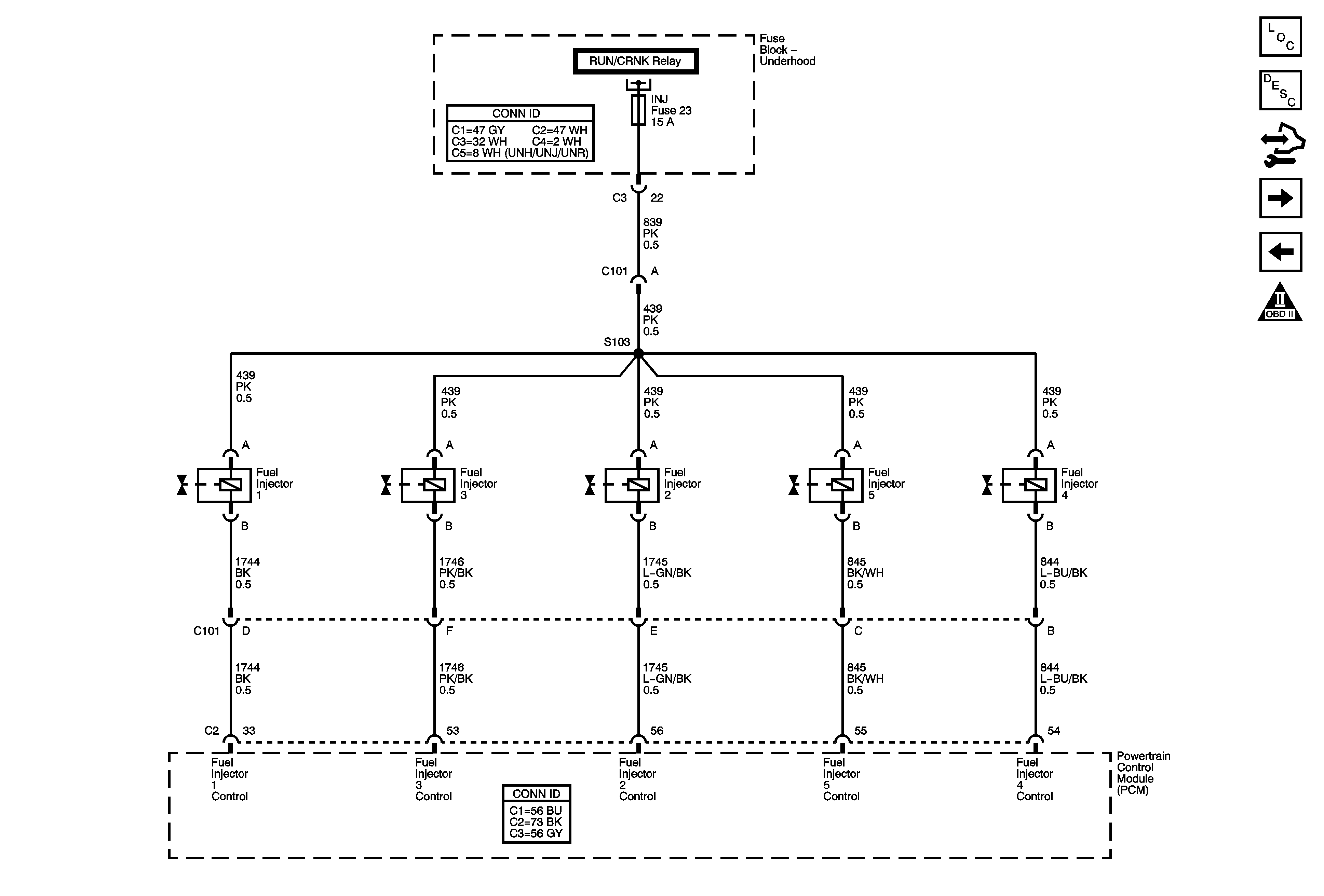
Figure 8:

Fuel Injection Controls


Object Number: 1776909  Size: FS
Master Electrical Component List
Powertrain Control Module Description
Control Module References
Fuel and EVAP Controls
Fuel Controls
Engine Controls Schematic Icons
Module Power, Ground, Serial Data, MIL, and DLC
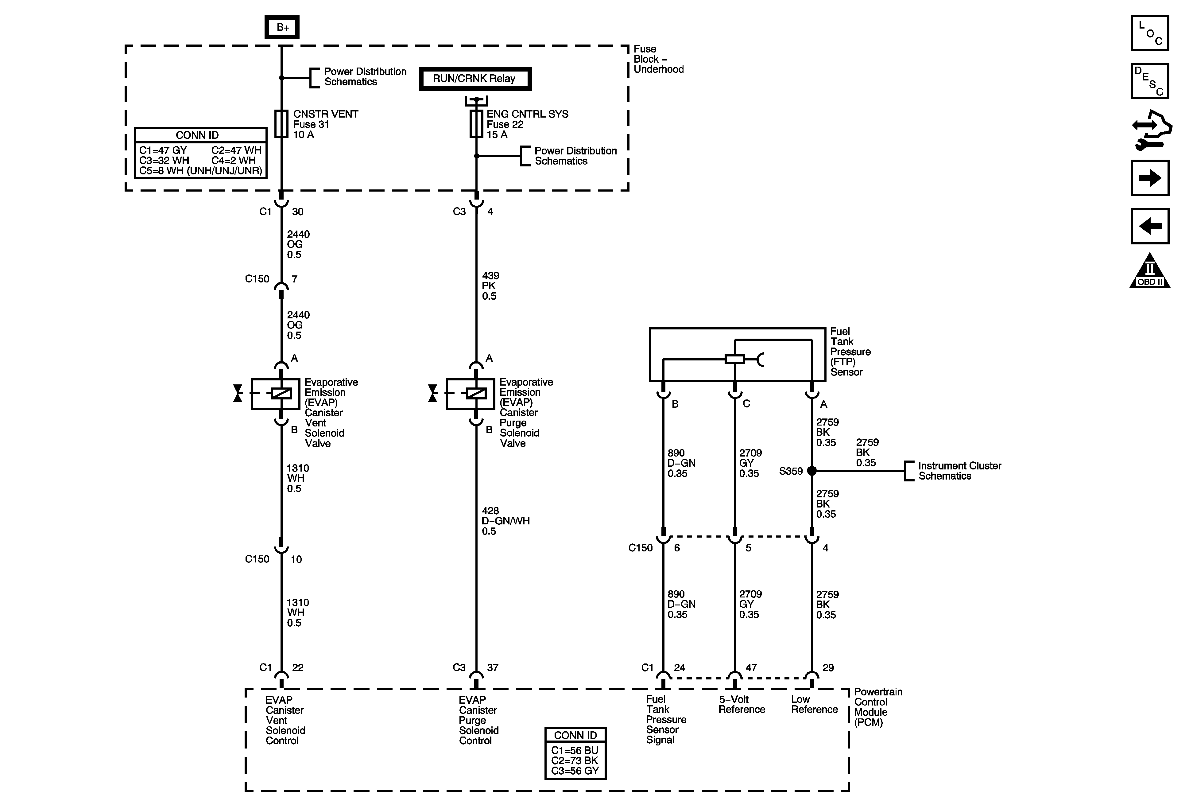
Figure 9:

Fuel and EVAP Controls


Object Number: 1776918  Size: FS
Master Electrical Component List
Powertrain Control Module Description
Control Module References
Device Controls - K18
Fuel Injection Controls
Engine Controls Schematic Icons
B+ Bus - Underhood Fuse Block - 1 of 2
Module Power, Ground, Serial Data, MIL, and DLC
RUN/CRNK Relay Bus - 3 of 3, ENG CNTRL SYS, INJ, and PCM-I Fuses
Gages
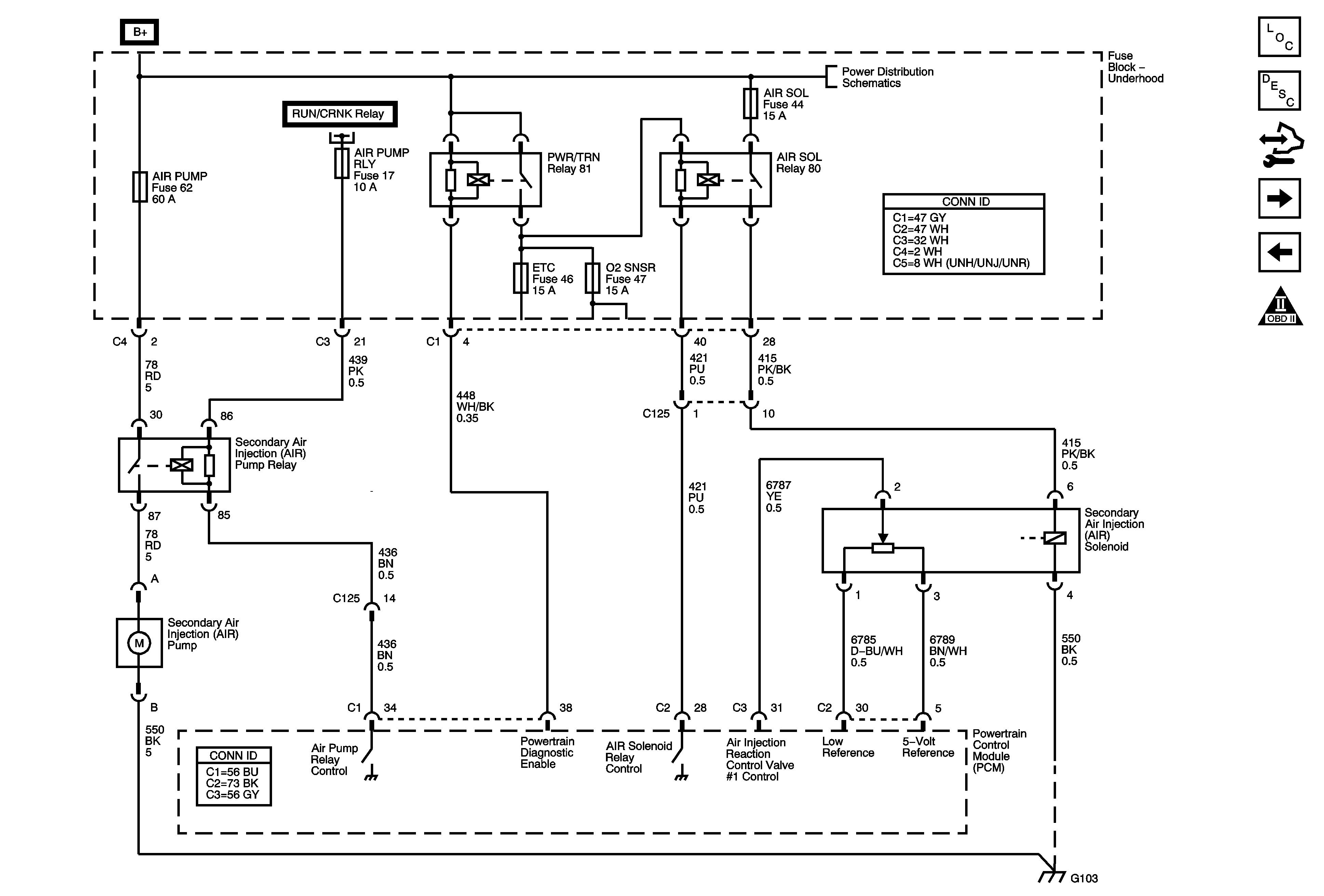
Figure 10:

Device Controls- K18


Object Number: 1824859  Size: FS
Master Electrical Component List
Powertrain Control Module Description
Control Module References
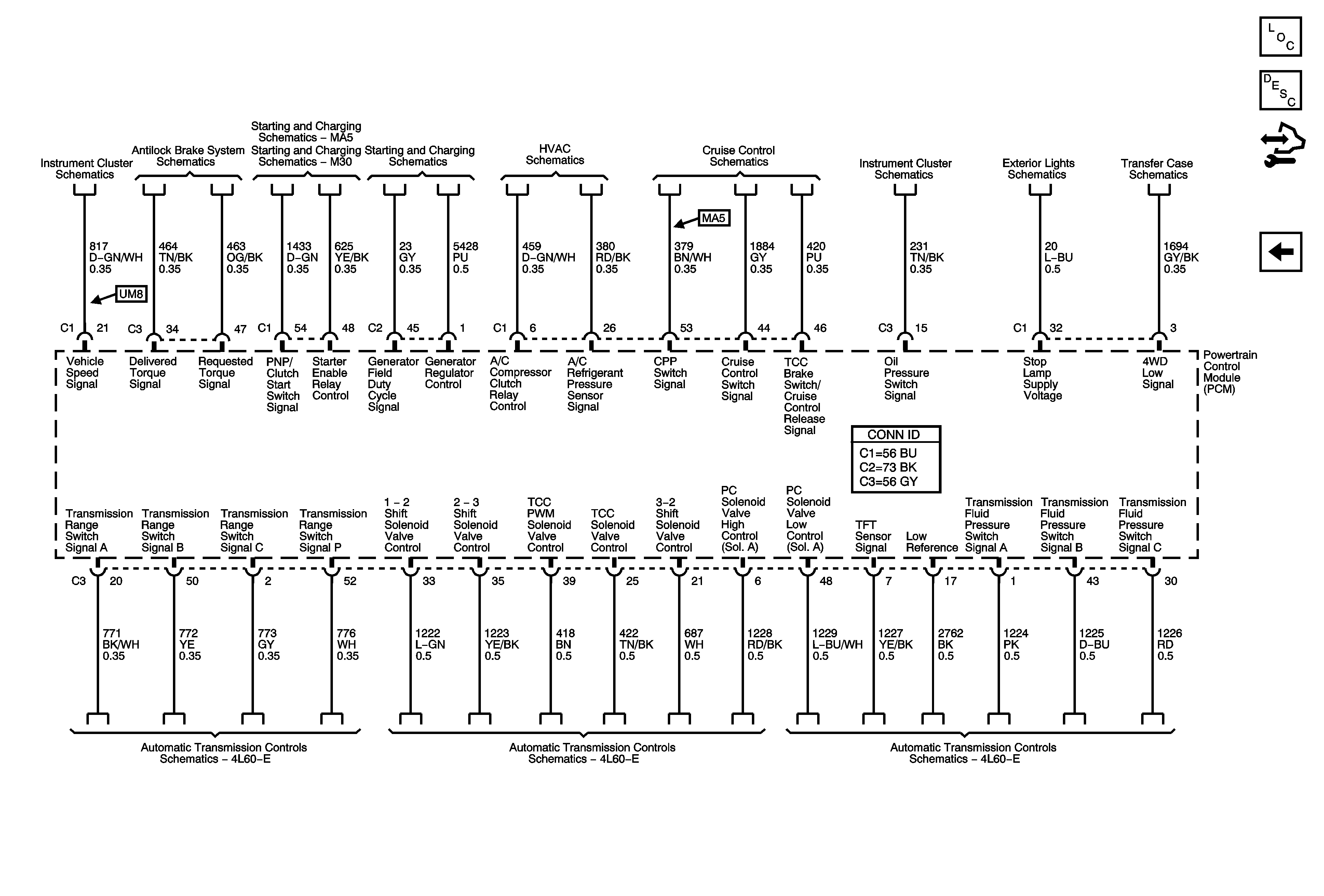
Controlled/Monitored Subsystem and Transmission References
Fuel and EVAP Controls
Engine Controls Schematic Icons
Module Power, Ground, Serial Data, MIL, and DLC
G100, G102, G103, G104, G110, and G120
Figure 11:

Controlled/Monitored Subsystem and Transmission References


Object Number: 1776929  Size: FS
Master Electrical Component List
Powertrain Control Module Description
Control Module References
Device Controls - K18
Engine Controls Schematic Icons
Gages
Power, Ground, and Electronic Brake Control Module (EBCM)
Starting System - MA5
Starting System - M30
Charging System
Compressor Controls
Cruise Control Schematics
Indicators
Center High Mount Stop Lamps (CHMSL) and Stop Lamp Switch
Power, Ground, Serial Data, Indicator, VSS and Encoder Motor
Switches
Transmission Controls
TCC Brake/Cruise Release Switch and Vehicle Speed Sensor