Brake Master Cylinder with Power Brake Booster and Chassis Control Module Replacement LHD
Removal Procedure
Caution: Refer to Brake Fluid Irritant Caution in the Preface section.
Notice: Refer to Brake Fluid Effects on Paint and Electrical Components Notice in the Preface section.
- Apply and release the brake pedal 20 times to deplete the hydraulic brake booster accumulator reserve.
- Remove the rear and left front brake pipes from the brake master cylinder.
- Remove the right front brake pipe from the brake master cylinder.
- Disconnect the electrical connectors at the brake pressure modulator valve (BPMV).
- Disconnect the electrical connector for the fluid level sensor.
- Remove the knee bolster. Refer to Driver Knee Bolster Replacement .
- Remove the knee bolster bracket. Refer to Driver Knee Bolster Bracket Replacement .
- Remove the retainer from the clevis pin.
- Remove the clevis pin from the master cylinder push rod and the brake pedal.
- Remove the nuts for the brake master cylinder (2).
- Remove the brake master cylinder and power brake booster assembly (1).
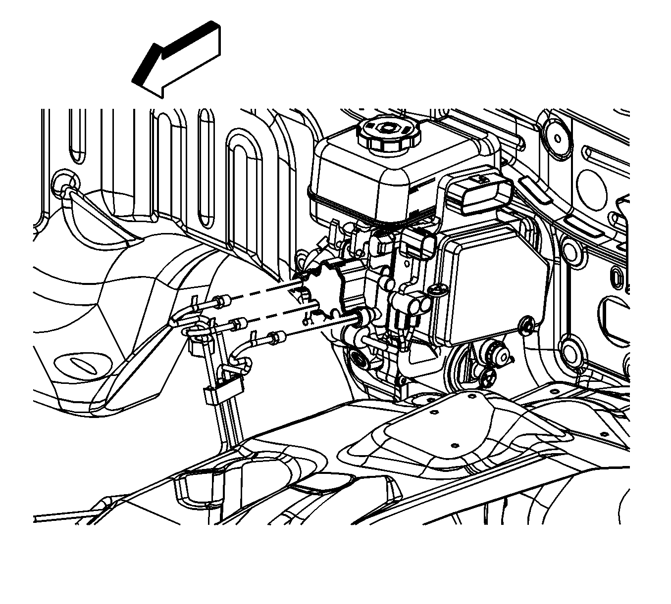
Cap the brake pipe fittings and plug the master cylinder outlet ports to prevent brake fluid loss and contamination.
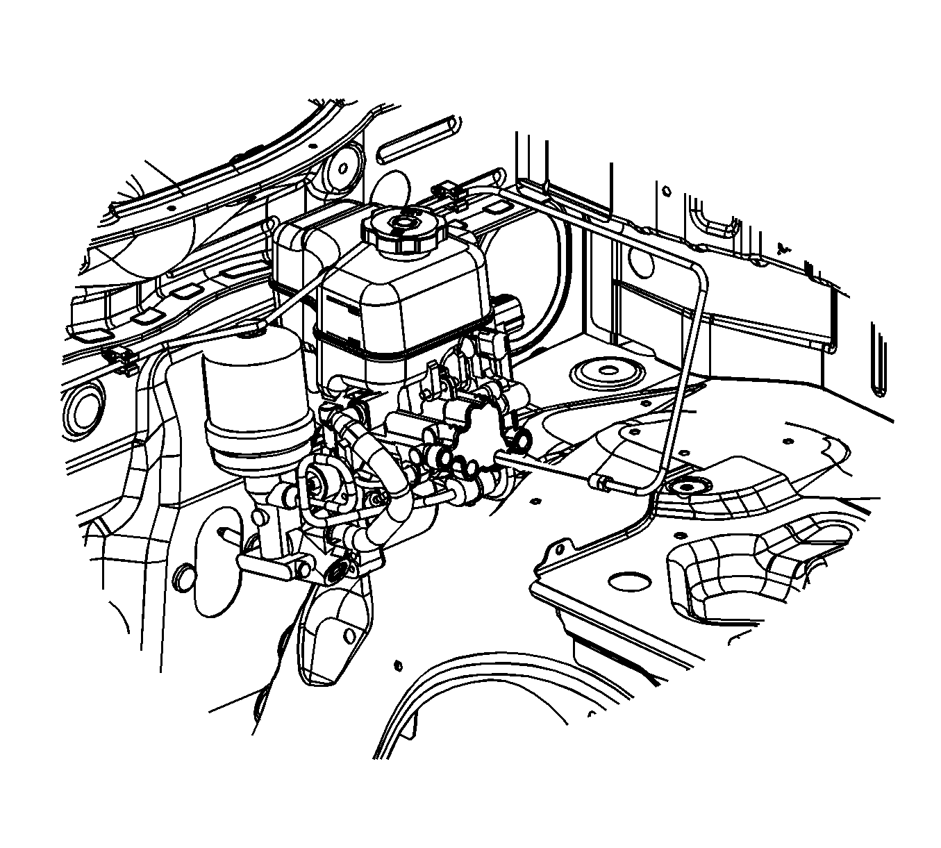
Cap the brake pipe fittings and plug the master cylinder outlet ports to prevent brake fluid loss and contamination.
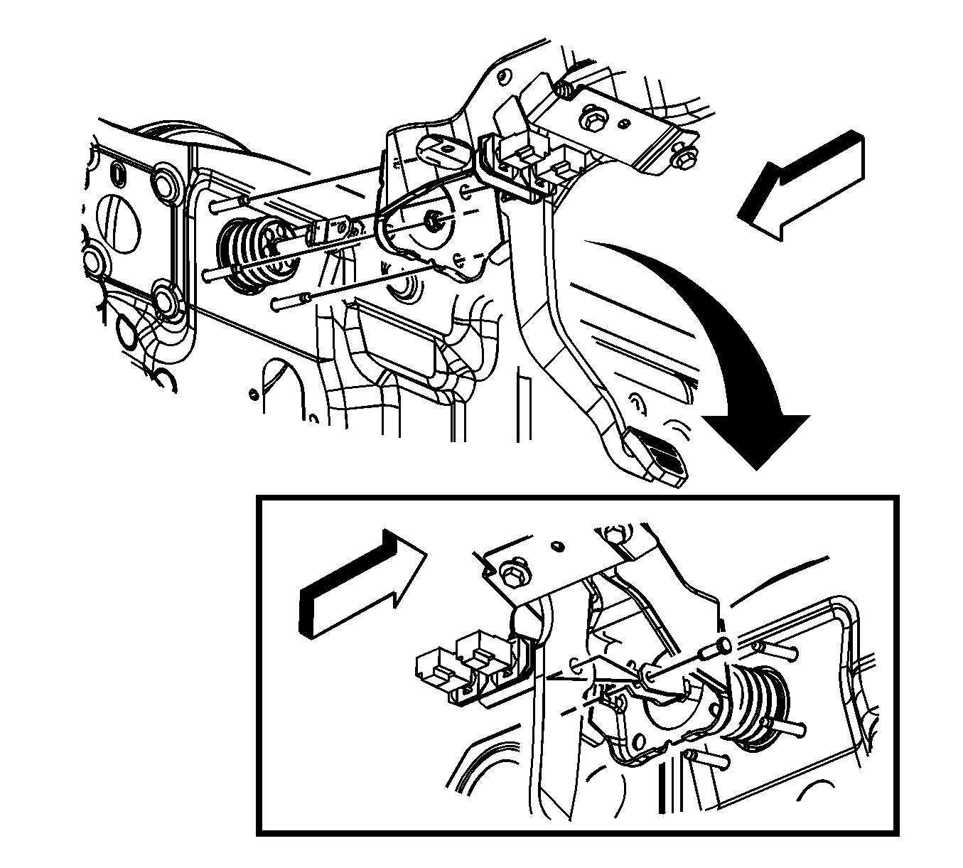
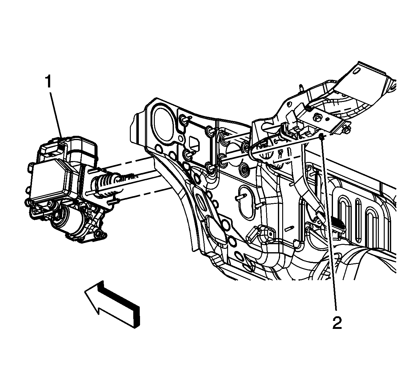
Important: It may be necessary to reposition or remove some of the wiring harnesses from their retainers to provide clearance to remove the mounting nuts for the brake master cylinder assembly.
Installation Procedure
- Install the brake master cylinder and power brake booster assembly (1).
- Install the master cylinder nuts (2).
- Install the clevis pin to the master cylinder push rod and the brake pedal.
- Install the retainer to the clevis pin.
- Install the knee bolster bracket. Refer to Driver Knee Bolster Bracket Replacement .
- Install the knee bolster. Refer to Driver Knee Bolster Replacement .
- Connect the electrical connector for the brake fluid level sensor.
- Connect the electrical connectors at the BPMV.
- Install the right front brake pipe fitting to the master cylinder.
- Install the rear and left front brake pipe fittings to the brake master cylinder.
- Adjust the stop lamp switch. Refer to Stop Lamp Switch Adjustment .
- Bleed the brake system. Refer to Hydraulic Brake System Bleeding .

Notice: Refer to Fastener Notice in the Preface section.
Tighten
Tighten the nuts to 27 N·m (20 lb ft).


Tighten
Tighten the fittings to 19 N·m (14 lb ft).

Tighten
Tighten the fittings to 19 N·m (14 lb ft).
Brake Master Cylinder with Power Brake Booster and Chassis Control Module Replacement RHD
Removal Procedure
Caution: Refer to Brake Fluid Irritant Caution in the Preface section.
Notice: Refer to Brake Fluid Effects on Paint and Electrical Components Notice in the Preface section.
- Apply and release the brake pedal at least 20 times to release the power brake accumulator reserve pressure.
- Mark the location of the brake pipes to the master cylinder.
- Disconnect the 4 brake pipe fittings from the master cylinder.
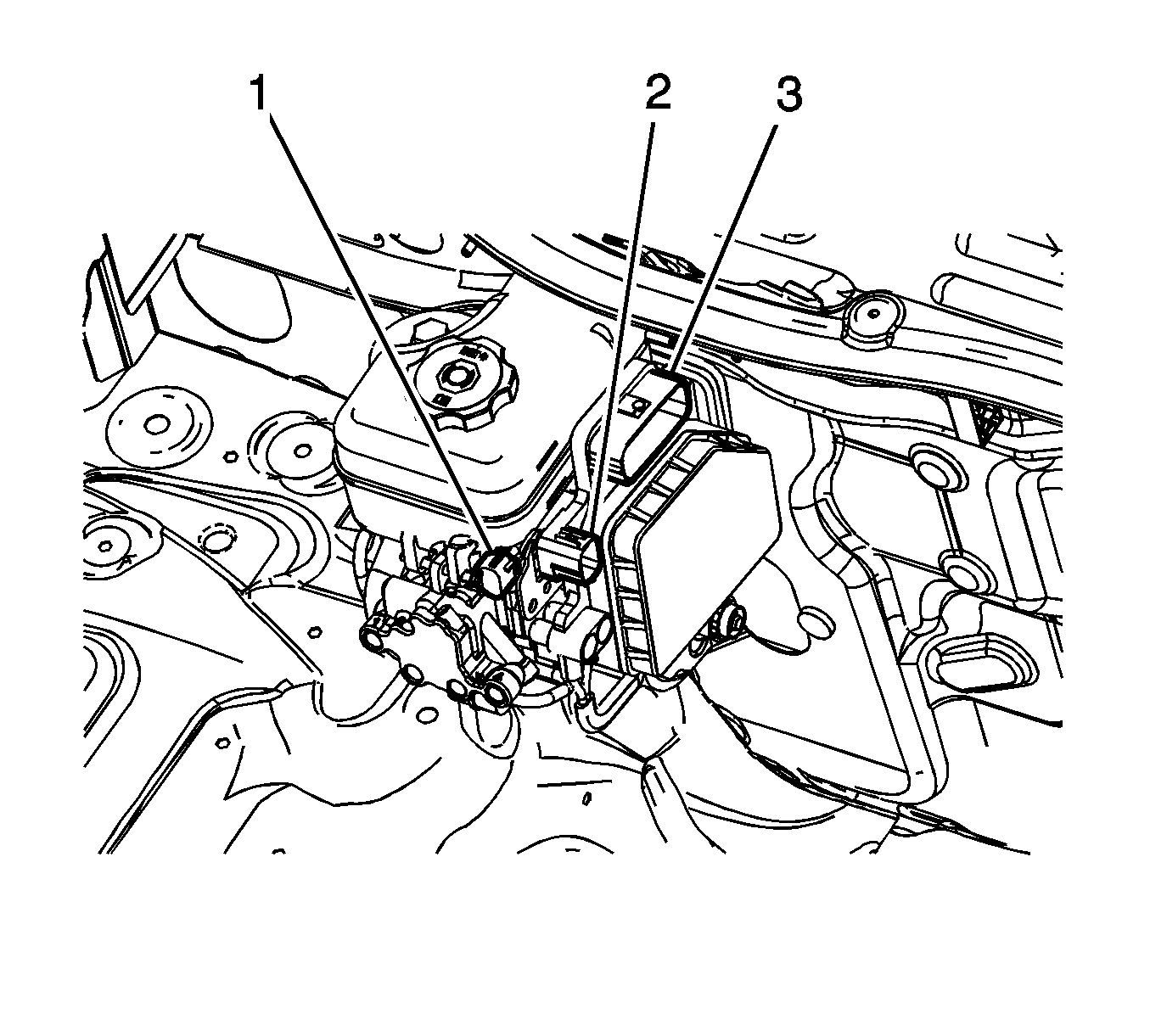
- Disconnect the brake fluid level sensor (1) electrical connector.
- Disconnect the electrical connectors (2) and (3) at the brake pressure modulator valve (BPMV) and module assembly.
- Remove the driver knee bolster bracket. Refer to Driver Knee Bolster Bracket Replacement .
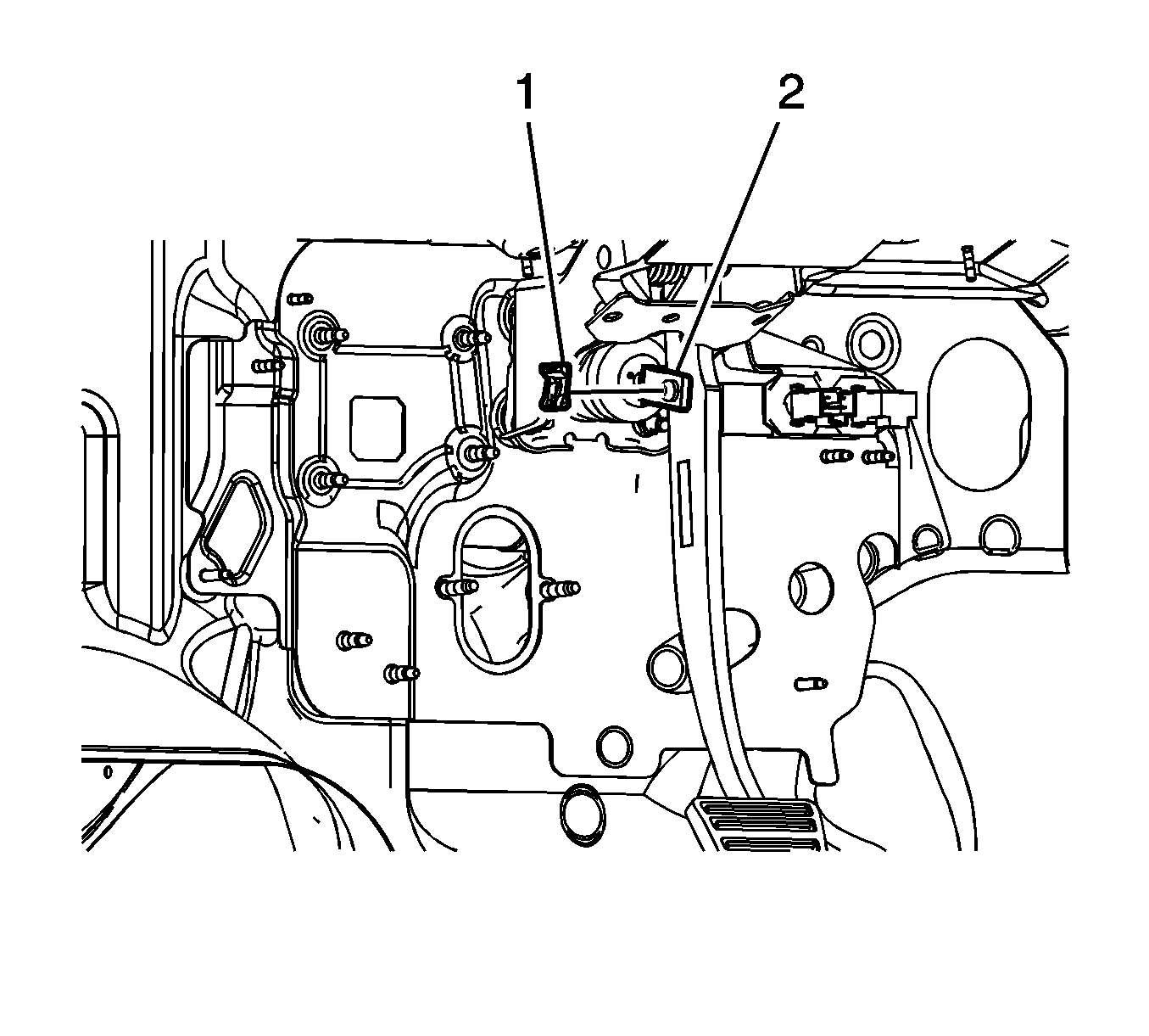
- Remove the retainer (1) from the clevis pin.
- Remove the clevis pin (2) from the master cylinder pushrod and the brake pedal.
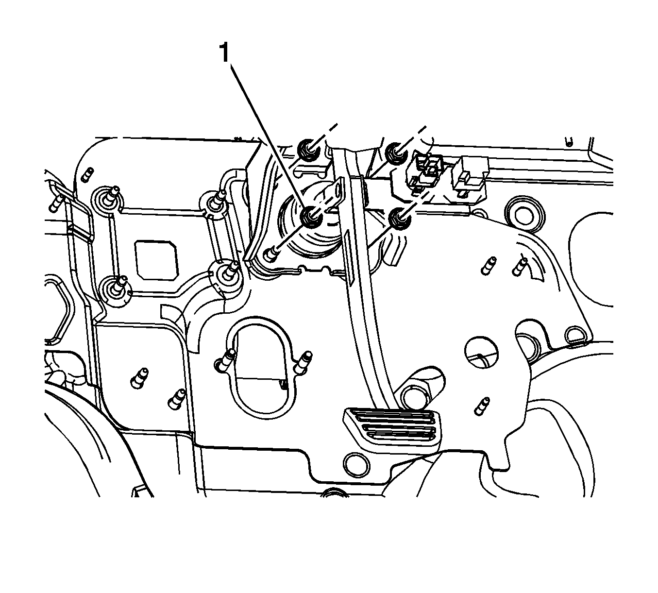
- Remove the 4 master cylinder nuts (1).
- Remove the master cylinder with power brake booster assembly.
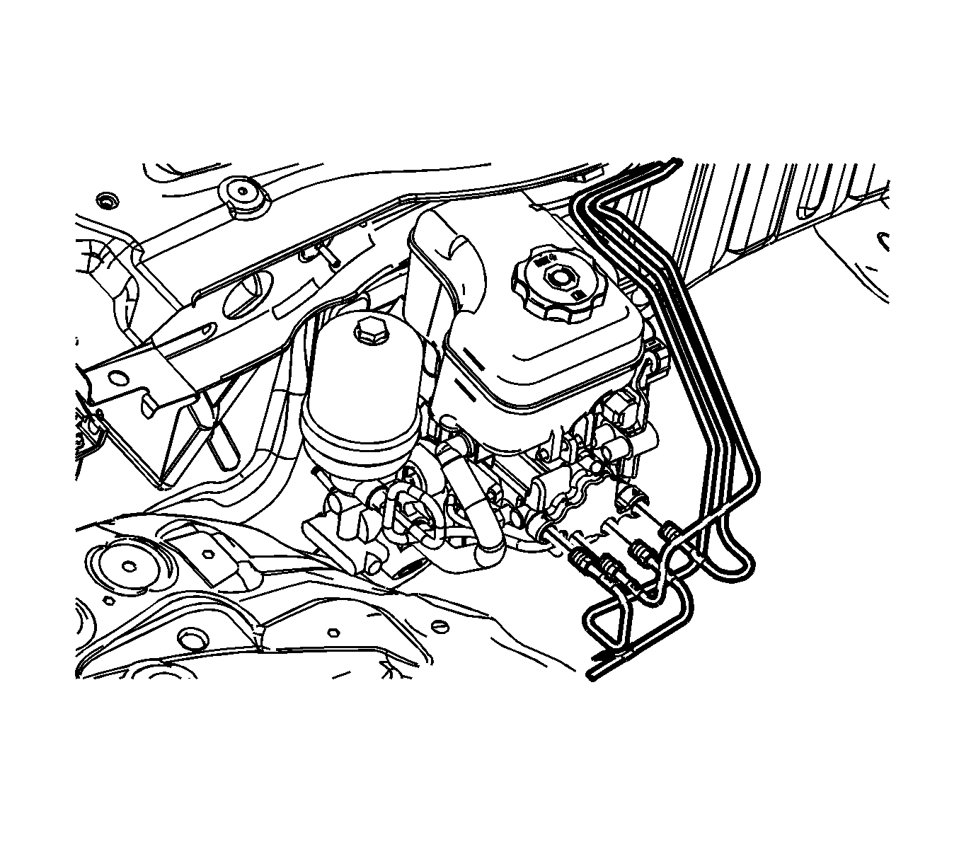
Cap the brake pipe fittings and plug the master cylinder outlet ports to prevent brake fluid loss and contamination.
Reposition any wiring harnesses as necessary to improve access to the master cylinder nuts.
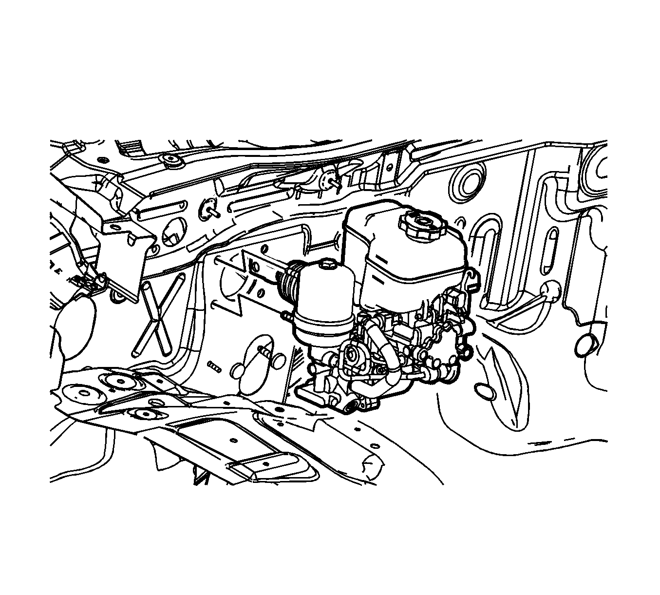
Installation Procedure
- Install the master cylinder with power brake booster assembly.
- Install the 4 master cylinder nuts (1).
- Position any wiring harnesses which were moved to access the master cylinder nuts to the retainers.
- Install the clevis pin (2) to the master cylinder pushrod and the brake pedal.
- Install the retainer (1) to the clevis pin.
- Verify the correct installation of the retainer by rotating the retainer 360 degrees.
- Install the driver knee bolster bracket. Refer to Driver Knee Bolster Bracket Replacement .
- Connect the brake fluid level sensor (1) electrical connector.
- Connect the electrical connectors (2) and (3) at the BPMV and module assembly.
- Connect the 4 brake pipe fittings to the master cylinder.
- Adjust the stop lamp switch. Refer to Stop Lamp Switch Adjustment .
- Adjust the cruise release switch. Refer to Cruise Release Switch Adjustment .
- Bleed the hydraulic brake system. Refer to Hydraulic Brake System Bleeding .

Notice: Refer to Fastener Notice in the Preface section.

Tighten
Tighten the nuts to 27 N·m (20 lb ft).

The retainer must rotate freely and not become disengaged from the groove in the clevis pin.


Tighten
Tighten the fittings to 19 N·m (14 lb ft).
