For 1990-2009 cars only
Removal Procedure
- Place the transmission in neutral.
- Release the park brake, if applied.
- Raise and support the vehicle. Refer to Lifting and Jacking the Vehicle .
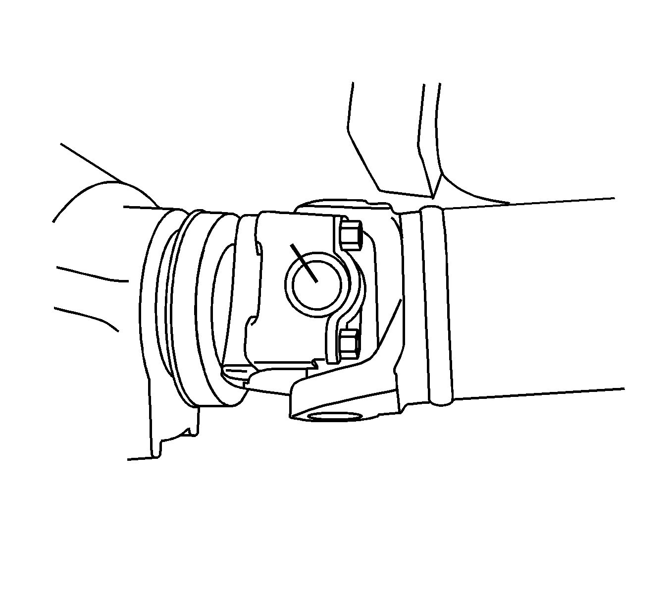
- Mark the front universal joint to the drive shaft flange.
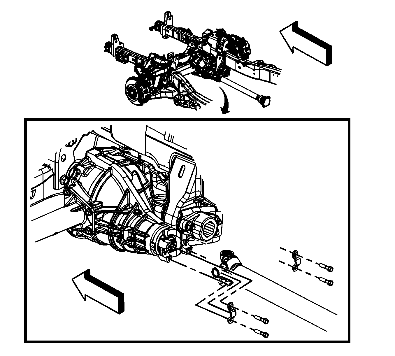
- Remove the retaining bolts and straps.
- Remove the propeller shaft from the front pinion drive flange.
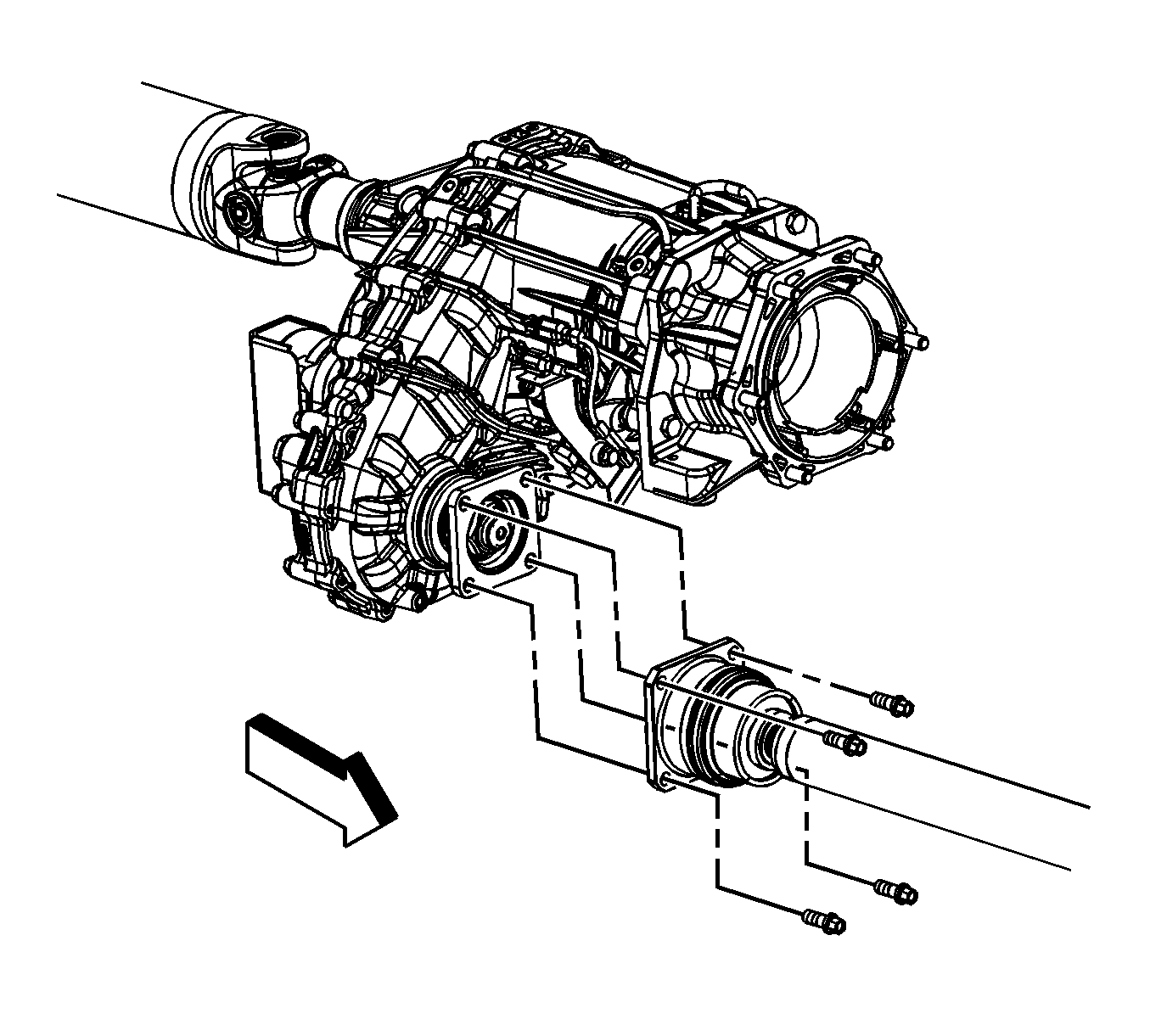
- Remove the propeller shaft retaining bolts.
- Remove the propeller shaft/CV joint from the transmission/transfer case flange.
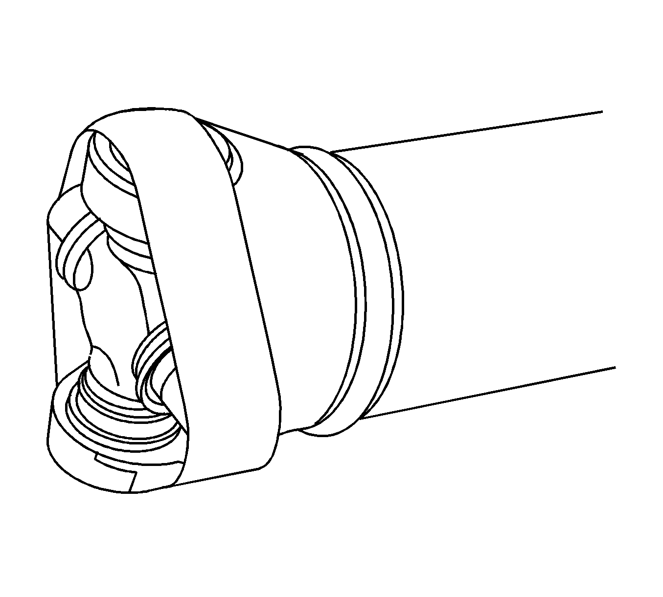
- Using tape or a rubber band, wrap the U-Joint bearing caps to ensure the bearing caps do not separate from the U-Joint.


Installation Procedure
- Remove the tape or rubber band from the U-Joint.
- Position the propeller shaft/CV joint to the transmission/transfer case.
- Install the propeller shaft/CV joint retaining bolts.
- Align the propeller shaft with the reference marks on the pinion flange.
- Install the straps and retaining bolts.
- Lower the vehicle.

Notice: Refer to Fastener Notice in the Preface section.

Tighten
Tighten the retaining bolts to 61 N·m (45 lb ft).


Tighten
Tighten the retaining bolts to 25 N·m (18 lb ft).
