Park/Neutral Position and Backup Lamp Switch Replacement 3.7L
Tools Required
J 41364-A Park Neutral Switch Aligner
Removal Procedure
- Apply the parking brake.
- Shift the transmission into NEUTRAL.
- Raise and support the vehicle. Refer to Lifting and Jacking the Vehicle .
- Remove the nut securing the transmission control lever to the manual shaft.
- Remove the transmission control lever from the manual shaft.
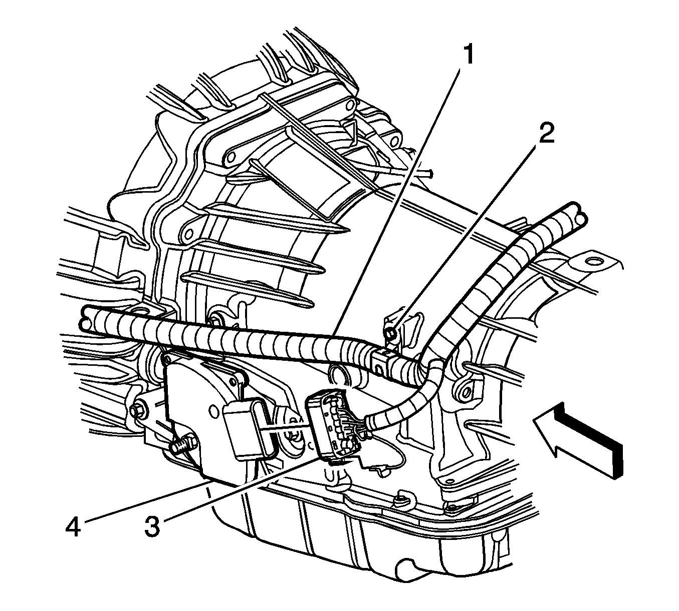
- Disconnect the electrical connector (3) from the switch (4).
- Remove the bolts securing the park/neutral back up switch to the transmission.
- Remove the park/neutral back up switch from the manual shaft.
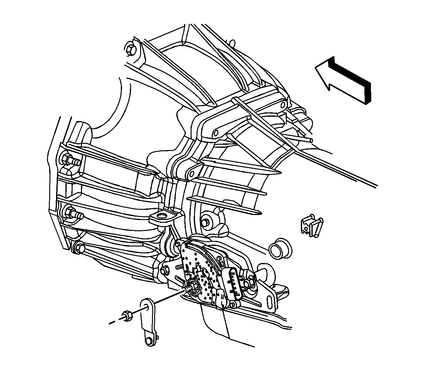
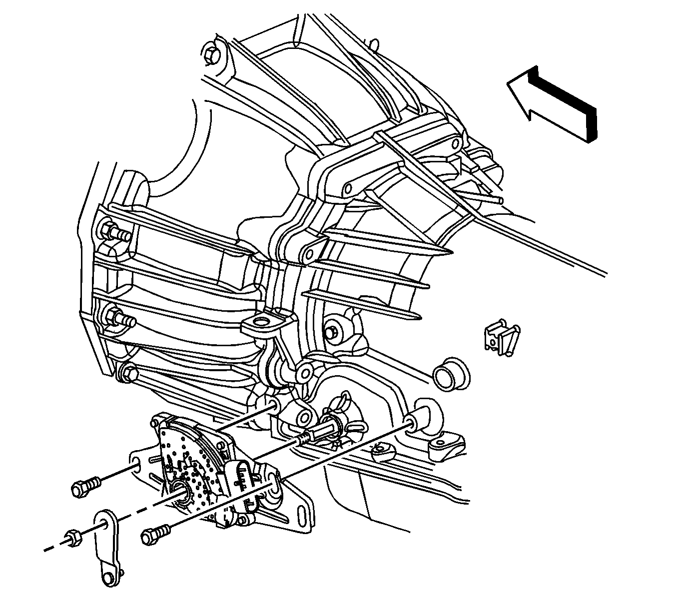
Important: If the switch does not slide off the manual shaft, the outer edge of the manual shift shaft may need to be filed to remove any burrs.
Installation Procedure
- Install the park/neutral back up switch to the transmission manual shaft by aligning the switch hub flats with the manual shaft flats.
- Slide the switch onto the transmission manual shaft until the switch mounting bracket contacts the mounting bosses on the transmission.
- Loosely install the 2 park/neutral back up switch bolts.
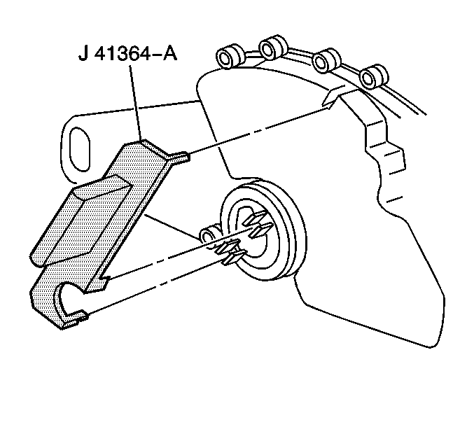
- Position the J 41364-A onto the park/neutral back up switch. Ensure that the 2 slots on the switch where the manual shaft is inserted are lined up with the lower 2 tabs on the tool.
- Rotate the switch until the upper locator pin on the tool is lined up with the slot on the top of the switch.
- Remove the J 41364-A from the switch. If installing a new switch, remove the positive assurance bracket at this time.
- Connect the electrical connector (3) to the switch (4).
- Install the transmission control lever to the manual shaft with the nut.
- Lower the vehicle.
- Adjust the automatic transmission range selector cable. Refer to Range Selector Lever Cable Adjustment .
- Check the switch for proper operation. The engine must start in the P (PARK) or N (NEUTRAL) positions only. If proper operation of the switch can not be obtained, replace the switch.

Important: If a new switch is being installed, the switch will come with a positive assurance bracket. The positive assurance bracket aligns the new switch in the proper position for installation and the use of the J 41364-A will not be necessary.
Notice: Refer to Fastener Notice in the Preface section.
Tighten
Tighten the park/neutral back up switch bolts 27 N·m (20 lb ft).


Tighten
Tighten the control lever nut to 20 N·m (15 lb ft).
Park/Neutral Position and Backup Lamp Switch Replacement 5.3L
Tools Required
J 41364-A Park Neutral Switch Aligner
Removal Procedure
- Apply the parking brake.
- Shift the transmission into NEUTRAL.
- Raise and support the vehicle. Refer to Lifting and Jacking the Vehicle .
- Remove the left catalytic converter. Refer to Catalytic Converter Replacement - Left Side .
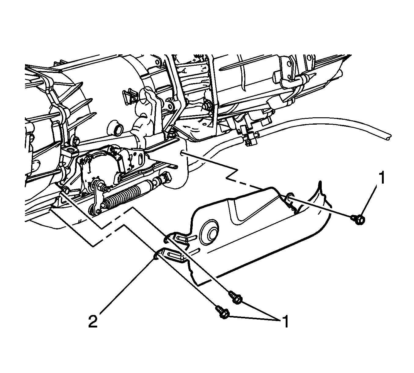
- Remove the heat shield bolts (1).
- Remove the heat shield (2).
- Disconnect the range selector cable end (3) from the range selector lever.
- Remove the retainer (1) from the range selector cable (2).
- Push the range selector cable locking tabs (2) inward toward each other to release the cable from the bracket.
- Remove the nut securing the transmission control lever to the manual shaft.
- Remove the transmission control lever from the manual shaft.
- Disconnect the electrical connector (3) from the switch (4).
- Remove the bolts securing the park/neutral back up switch to the transmission.
- Remove the park/neutral back up switch from the manual shaft.
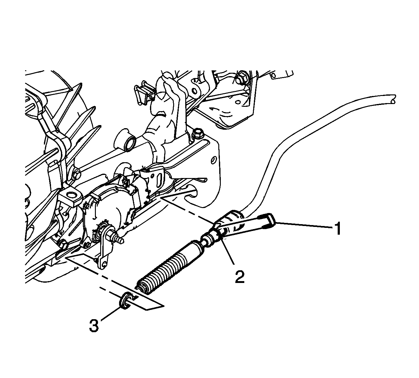
Important: Do not pull on the boot portion of the cable.


Important: If the switch does not slide off the manual shaft, the outer edge of the manual shift shaft may need to be filed to remove any burrs.
Installation Procedure
- Install the park/neutral back up switch to the transmission manual shaft by aligning the switch hub flats with the manual shaft flats.
- Slide the switch onto the transmission manual shaft until the switch mounting bracket contacts the mounting bosses on the transmission.
- Loosely install the 2 park/neutral back up switch bolts.
- Position the J 41364-A onto the park/neutral back up switch. Ensure that the 2 slots on the switch where the manual shaft is inserted are lined up with the lower 2 tabs on the tool.
- Rotate the switch until the upper locator pin on the tool is lined up with the slot on the top of the switch.
- Remove the J 41364-A from the switch. If installing a new switch, remove the positive assurance bracket at this time.
- Connect the electrical connector (3) to the switch (4).
- Install the transmission control lever to the manual shaft with the nut.
- Install the range selector cable (2) to the range selector cable bracket. Ensure the range selector cable retaining tabs fully engage the range selector cable bracket.
- Install the retainer (1) to the range selector cable (2).
- Connect the range selector cable end (3) to the transaxle range switch lever.
- Install the heat shield (2).
- Install the heat shield bolts (1).
- Install the left catalytic converter. Refer to Catalytic Converter Replacement - Left Side .
- Lower the vehicle.
- Adjust the automatic transmission range selector cable. Refer to Range Selector Lever Cable Adjustment .
- Check the switch for proper operation. The engine must start in the P (PARK) or N (NEUTRAL) positions only. If proper operation of the switch can not be obtained, replace the switch.

Important: If a new switch is being installed, the switch will come with a positive assurance bracket. The positive assurance bracket aligns the new switch in the proper position for installation and the use of the J 41364-A will not be necessary.

Notice: Refer to Fastener Notice in the Preface section.
Tighten
Tighten the park/neutral back up switch bolts 27 N·m (20 lb ft).


Tighten
Tighten the control lever nut to 20 N·m (15 lb ft).


Tighten
Tighten the bolts to 10 N·m (89 lb in).
