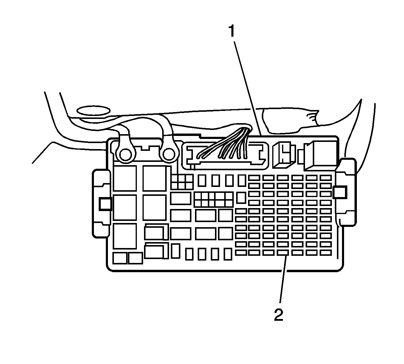
- Follow the Wiring Systems sub-section for splicing wires using splice sleeves. Refer to Splicing Copper Wire Using Splice Sleeves .
- Remove the ground terminal of the battery. Refer to Battery Negative Cable Disconnection and Connection .
- Ensure the vehicle is in the park (P) position.
- Apply park brake.
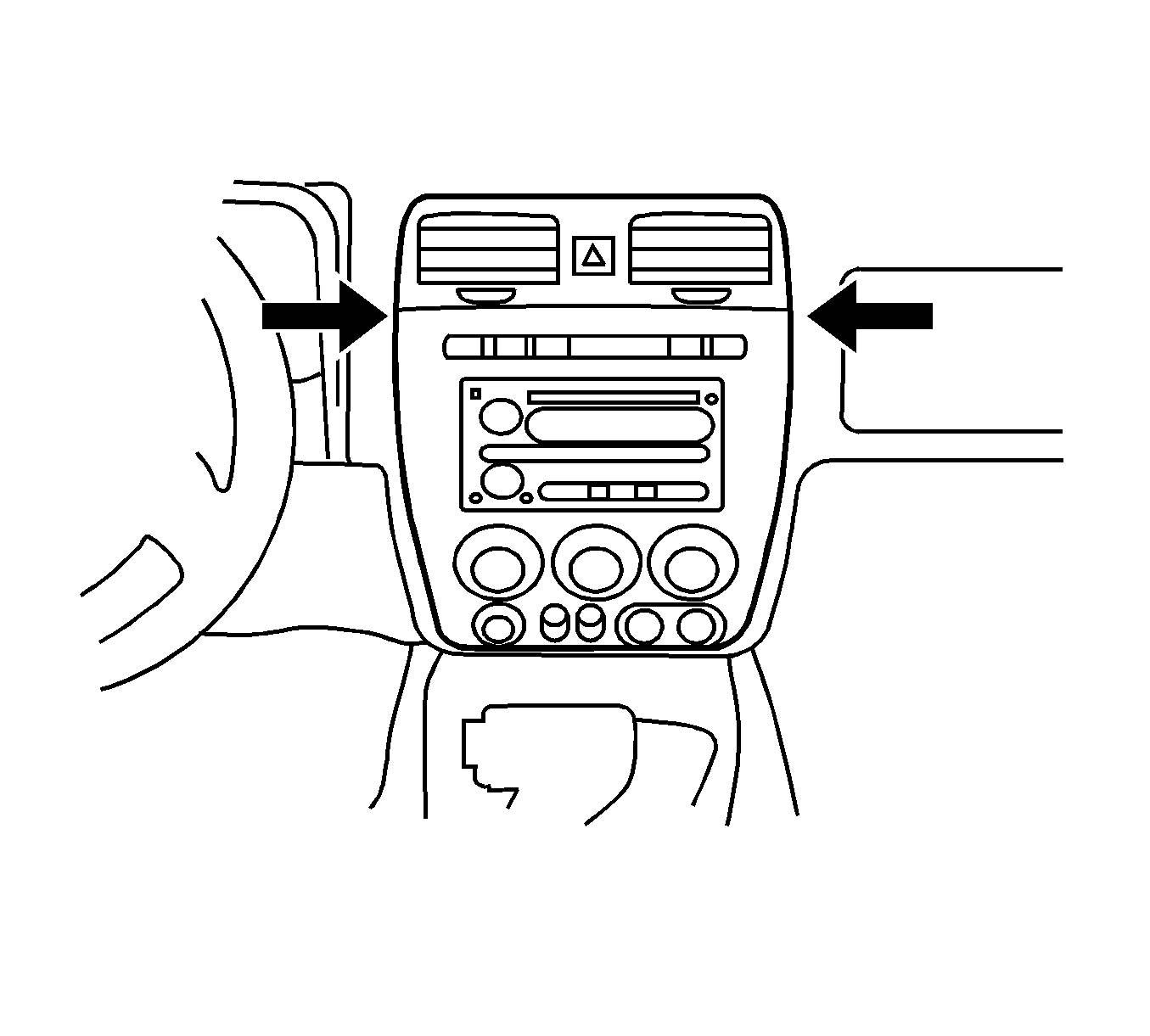
- Using a flat-bladed tool, press inward at the sides of the radio trimplate in order to release the clips.
- Press in on both sides if the trimplate just below the HVAC vents.
- Gently remove the trimplate.
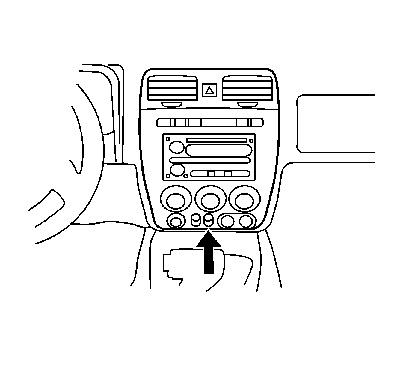
- Remove the switch plug next to the auxiliary power outlet by flexing open the retention walls on the back of the trimplate and pushing the plug from the front of the trimplate at the same time.
- Snap the switch into the open position from the rear of the trimplate.
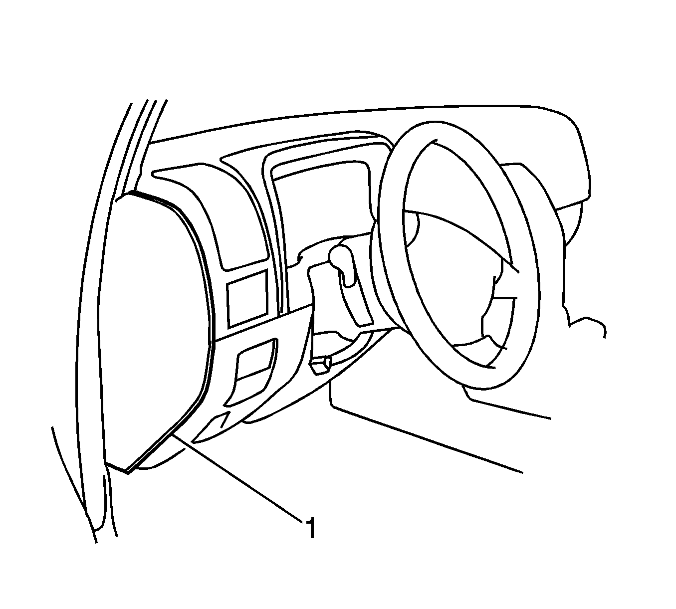
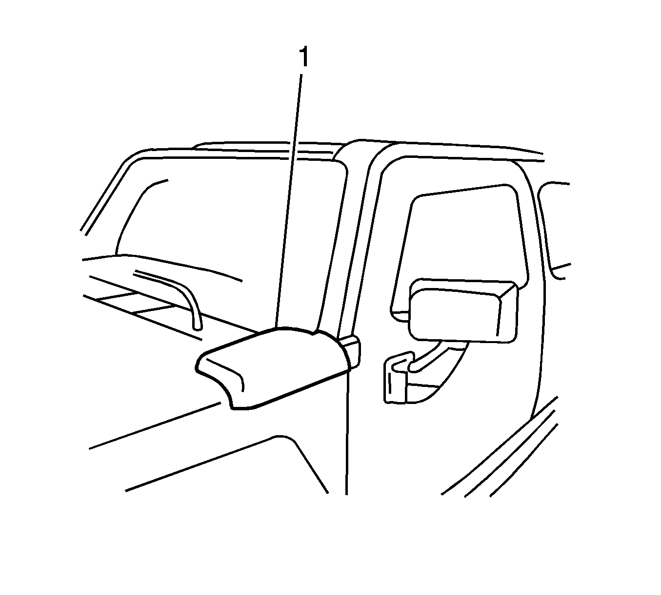
- Remove the instrument panel (I/P) end cover trim panel (1) by gently prying the outer edge with a flat-bladed tool in order to release the clips.
- Remove the I/P lower trim plate by releasing the clips and pulling from the lower right side first.
- Remove the hood release handle and cable by removing the screws and pressing forward in the vehicle to disengage the tabs.
- Route the switch connector harness up from the driver's side floor behind the I/P center console.
- Connect the switch connector to the switch.
- Reinstall the I/P trimplate by positioning the trimplate and pressing in at the retention clip locations.
- Locate the black blunt cut wire (1) on the right side of the driver footwell above the footwell lamp.
- Tape this wire up onto the harness (2).
- Splice this wire to the black wire in Pin B of the switch connector and use the splice sleeve to connect the wire.
- Use the splice sleeve to connect the appropriate ground wires together.
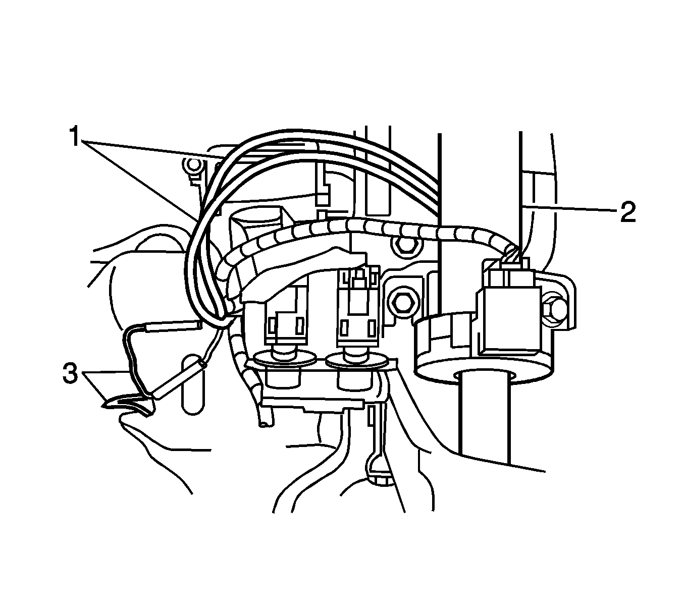
- Route the orange and white wires from the switch (1) over the steering column support (2).
- Locate the blunt cut wires (3) under the I/P on the left side of the driver footwell above the park brake.
- These wires may be taped back onto the harness branch, cut the tape in order to free the wires.
- Splice the orange blunt cut wire to the orange wire in pin A of the switch connector using the splice procedure and the splice sleeves provided.
- Splice the white-striped, black blunt cut wire to the white wire in pin C of the switch connector using the splice procedure and the splice sleeves provided.
- Using tie straps, tie strap the wires to the other wire bundles out of the driver footwell area.
- Install the I/P lower trim plate by positioning the trim plate and pressing inward at the clip locations.
- Install the hood release cable and handle assembly by engaging the handle tab and installing the screws.
- Install the I/P end cover trim panel by positioning the panel and pressing inward at the clip locations.
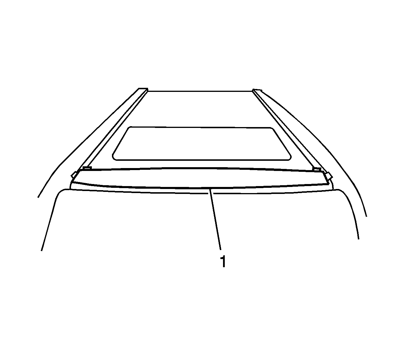
- Center the template provided (1) on the roof between the two A-pillars. Position the template so that the front edge rests against the rear edge of the windshield reveal molding and tape in place.
- Mark the 6 hole locations with a trip punch or center punch.
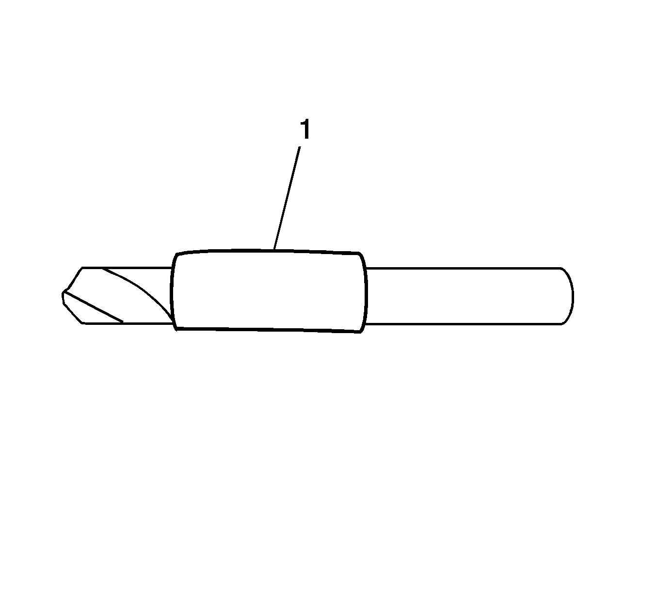
- Before drilling, add several wraps of tape (1) around end of drill bit to prevent the drill bit from penetrating through the roof into the headliner.
- Drill pilot holes with 2 mm (3/32 in) drill bit.
- Expand the holes with 6 mm (1/4 in) drill bit.
- Drill 9 mm holes in the 6 hole locations using the bit supplied within the kit.
- Clear all the metal shavings from around the holes with a magnet or vacuum.
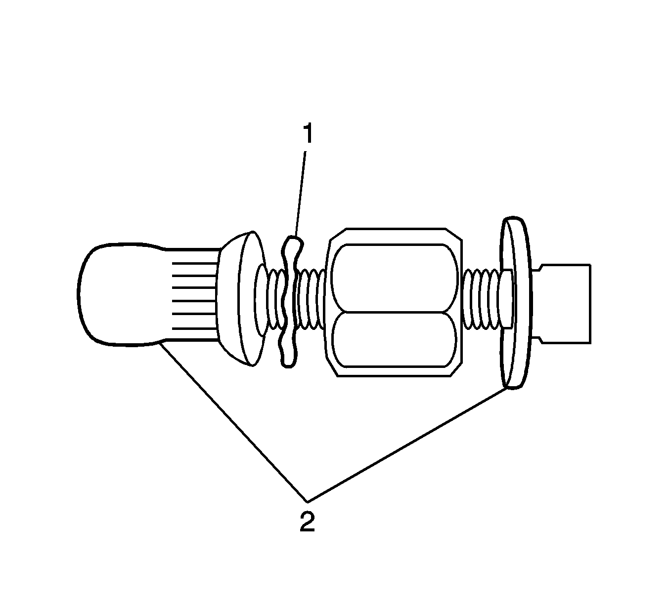
- Apply GM Superlube® with PTFE, GM P/N 12371287, to the lower half of the rivnut and between the washer and hex body of rivnut tool prior to inserting the rivnut into the hole.
- Ensure that the Star washer (1) is positioned on top of the rivnut tool (2) (all provided).
- Using a 5/16 inch box wrench in conjunction with a 1/2 inch open end wrench, secure the rivnuts to the roof panel.
- Secure each rivnut to the roof panel.
- Remove the air inlet cover (1) on the driver side by gently pulling upward to release the clips.
- Open the driver door.
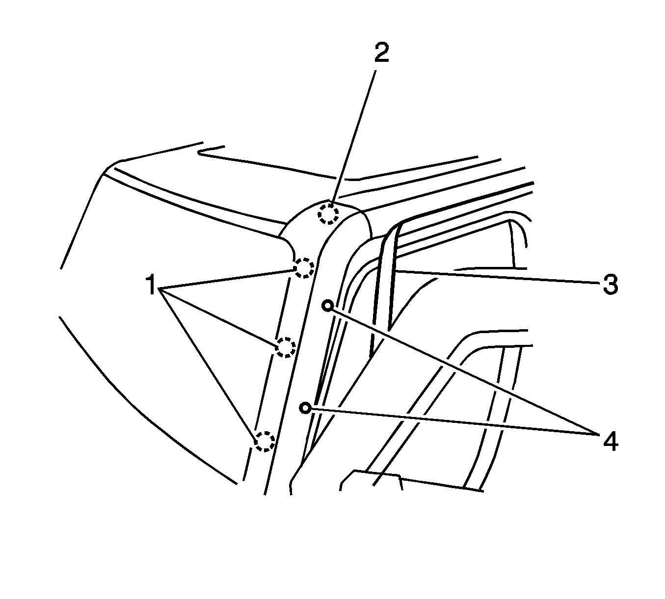
- Remove the exterior trim on both driver and passenger A-pillars by first peeling back the weatherstrip (3) to expose 2 screws (4).
- Using a phillips head screwdriver, remove the screws.
- Pull the lower end of the A-pillar trim to unsnap the clips (1).
- Disengage the A-pillar trim from the front end of the luggage rack/siderail (2) and remove.
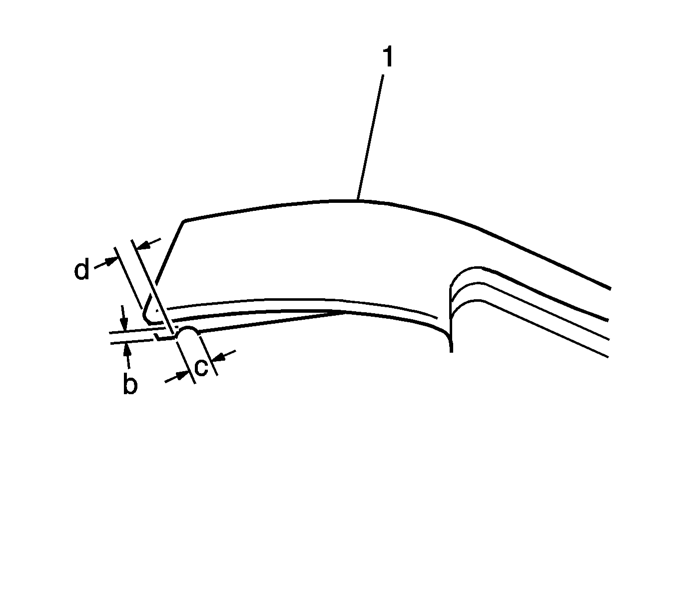
- Using diagonal cutters, clip a notch (c) in the driver side A-pillar (1) trim as shown for the wire entry.
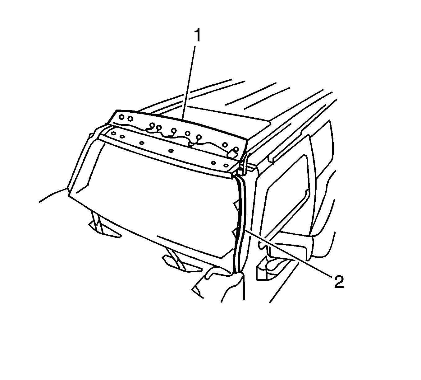
- Place the lightbar (1) and electrical harness assembly (2) upside down on the roof.
- Route the harness down the driver side A-pillar, placing it near the windshield glass interference to A-pillar and spot tape in 3 places.
- Ensure the harness lies flat and does not interfere with the snap locations for the A-pillar trim.
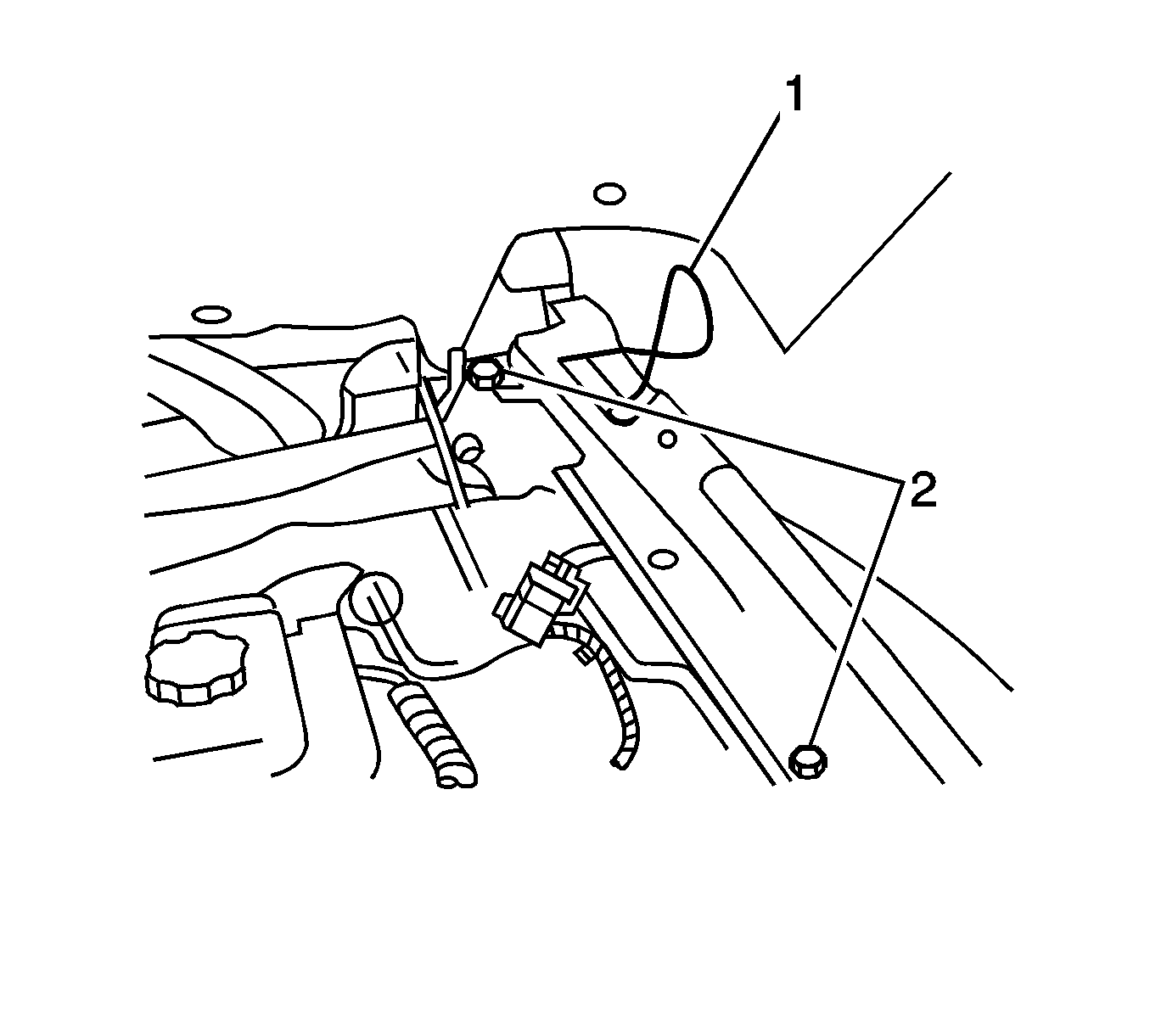
- Loosen the 2 screws (2) at the fender flange under the air inlet cover to allow the electrical harness (1) to pass underneath.
- Move the black foam out from under fender flange.
- Route the harness under the fender flange.
- Disconnect the relay, if necessary, to fit the harness through.
- Reconnect the relay, if necessary.
- Torque the fender flange attaching screws.
- Reposition the black foam under fender flange.
- Rotate the lightbar to the correct orientation on the roof.
- Position the front edge of light bar approximately 3 mm (1/8 in) rearward from the front edge of the windshield reveal molding. Using the 6 fasteners provided, and T25® Torx driver, install the lightbar to the roof.
- Secure the light bar to the roof.
- Ensure the lightbar is centered between A-pillars and adjust if necessary.
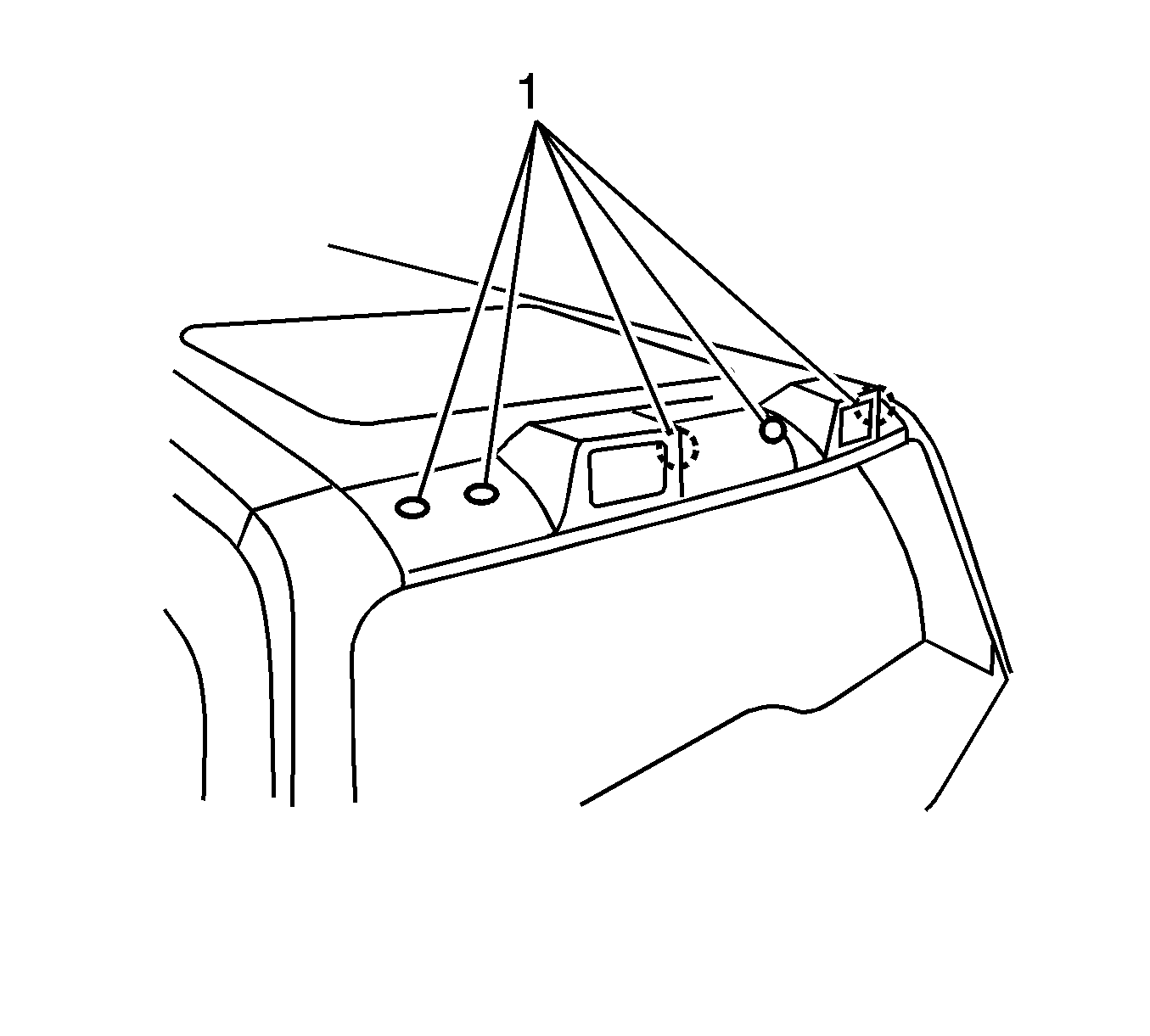
- Install the 6 fastener covers (1) by aligning the cover tab to the driver side and gently pressing in place.
- Install the A-pillar trim by hooking the rear edge and pressing the clips into place.
- Install the 2 screws behind the weatherstrip.
- Reposition the weatherstrip.
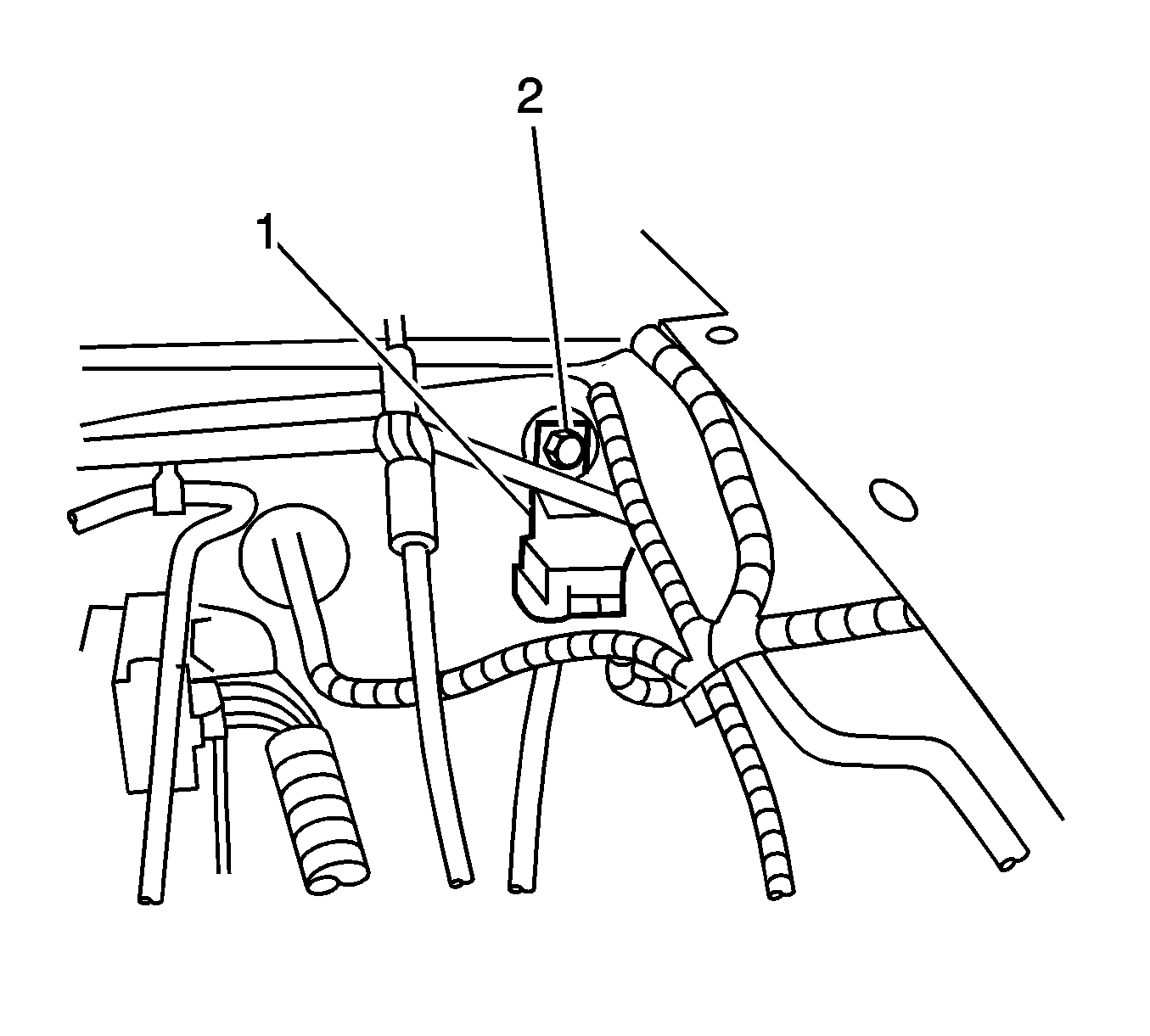
- In the engine compartment, locate the stud (2) on the driver side front of dash that holds the insulator mat in place.
- Hang the relay bracket (1) on this stud and secure with a palnut, provided in the kit.
- Locate the 6 blunt wiring cuts (1) in the engine compartment behind the driver side wheelhouse. The engine compartment blunt cuts have seals on them that must be removed prior to using the splice sleeve.
- Carefully remove some of the seal on the appropriate wire using a wiring stripping tool.
- Using the splice sleeve provided, splice the white-striped blunt black cut wire to the white wire in the electrical harness.
- Replace the conduit over the splice and tape the wiring in position.
- Splice the orange blunt cut to the orange harness wire using the splice sleeve provided.
- Replace the conduit over the splice and tape into place.
- Splice the black blunt cut wire from the vehicle to the black blunt cut wire in the harness using the splice sleeve provided.
- Replace the conduit over the splice and tape into place.
- Check the voltage or resistance to confirm.
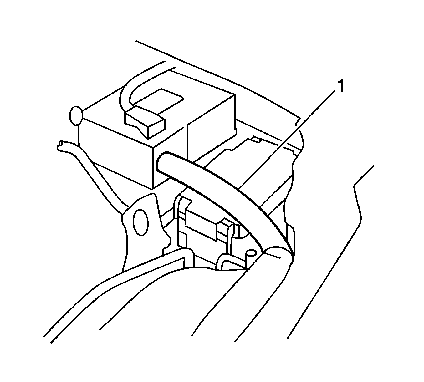
- Remove the battery vent tube (1) in order to access the bussed electrical center (BEC) .
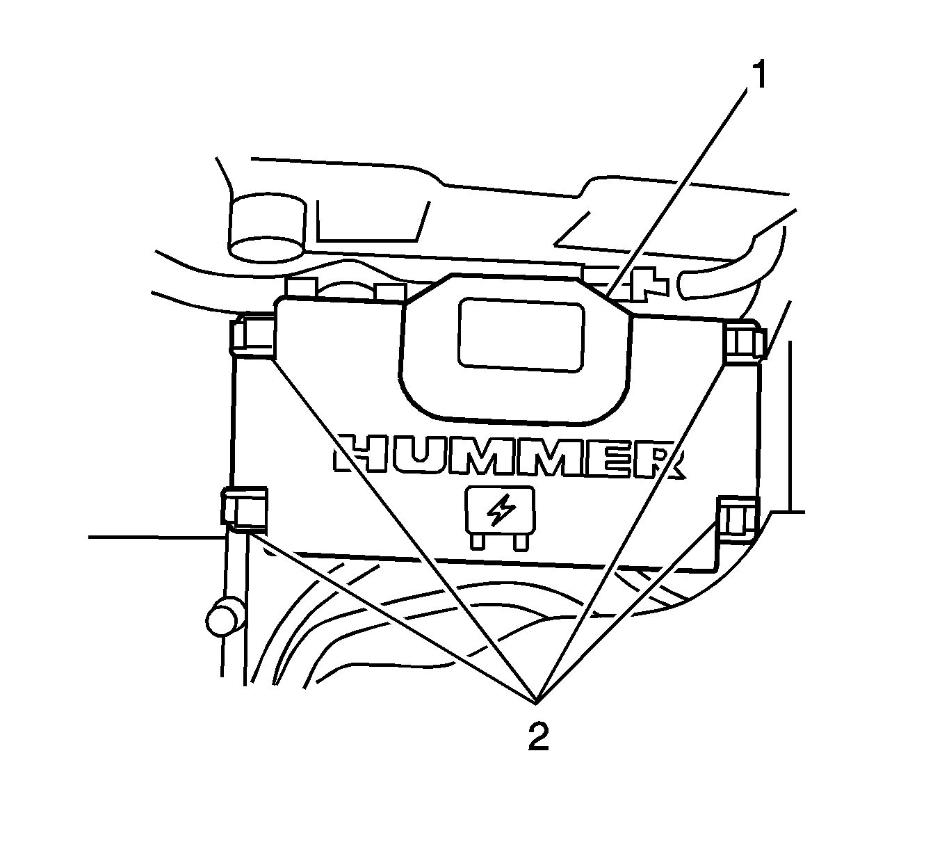
- Release the BEC cover (1) by depressing the locks (2) on both sides of cover simultaneously.
- Press the release the tabs (2) on the right and left sides.
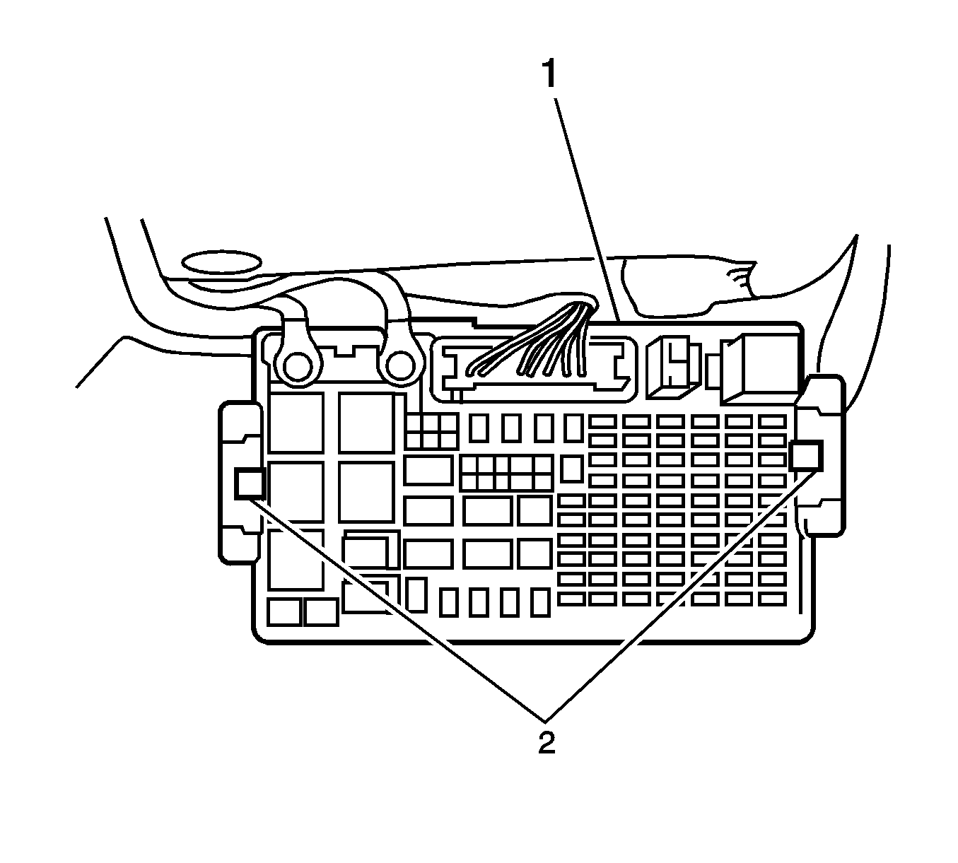
- Pull up on the BEC (1) using both hands.
- Locate the red harness wire that has a connector hanging from it.
- Plug the 8-way electrical connector (2) into the bottom of BEC (1) as shown.
- Reassemble the BEC by ensuring the 2 47-way connectors are in the upright and locked position. Ensure the locking fingers are engaged under the mating lock lug.
- Press downward and listen for an audible snap.
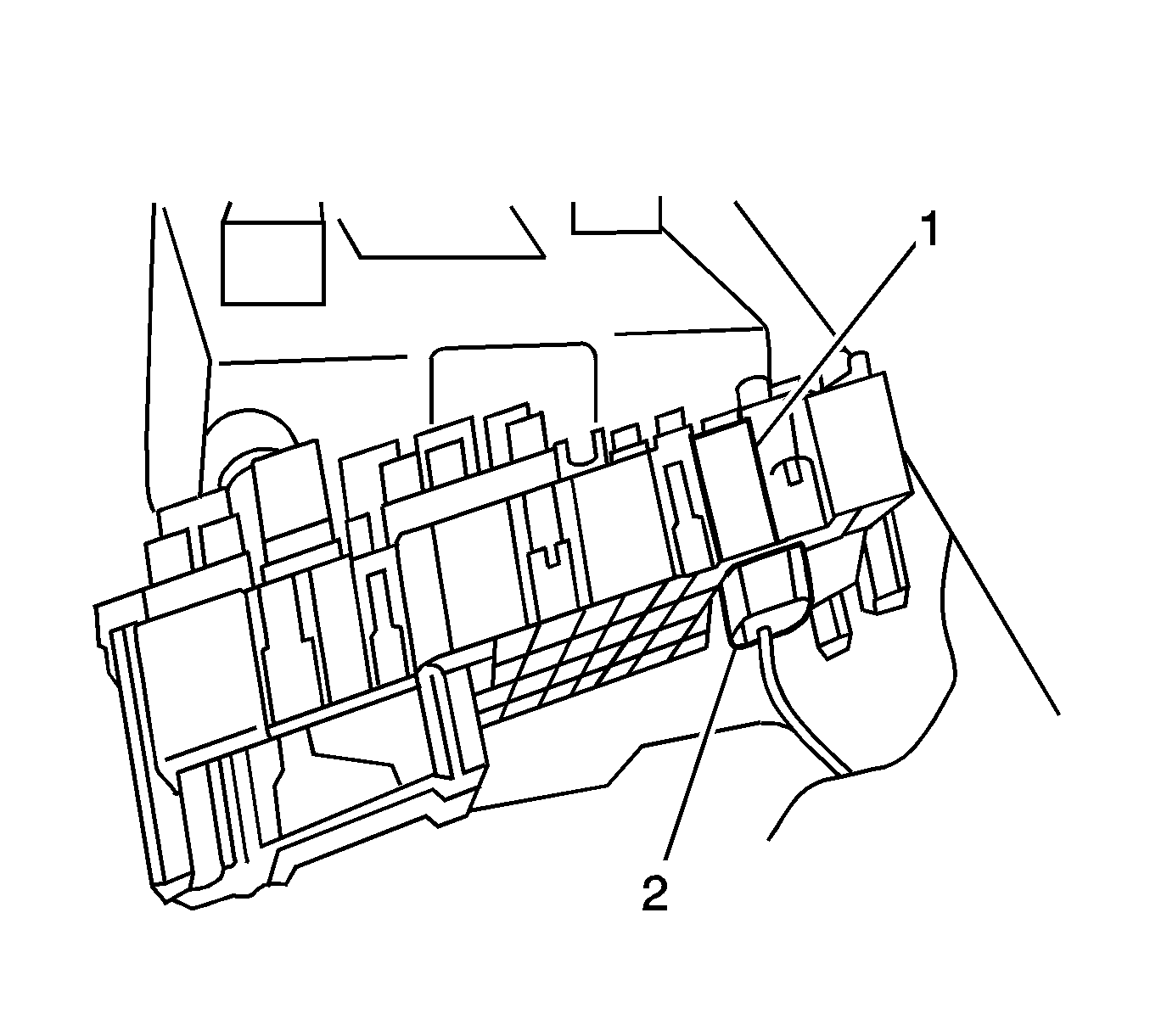
- Install the 20A fuse into location 4, callout (2), per the diagram inside of the BEC cover.
- Position the cover (1) over the 4 lock tabs (2). Ensure the appropriate wire routing to avoid trapping wires.
- Press the cover downward and listen for an audible snap.
- Install the battery vent tube.
- Connect the negative battery cable. Refer to Battery Negative Cable Disconnection and Connection .
- Remove the lamp covers.
- Press the lamp switch and verify the lamps are working.
- Adjust the lamps, if needed. Refer to Off Road Lamp Adjustment .
- Place the vehicle in park transmission position.
- Disengage the park brake.
Important: Ensure the taped portion of the harness extends beyond the I/P center console brackets.
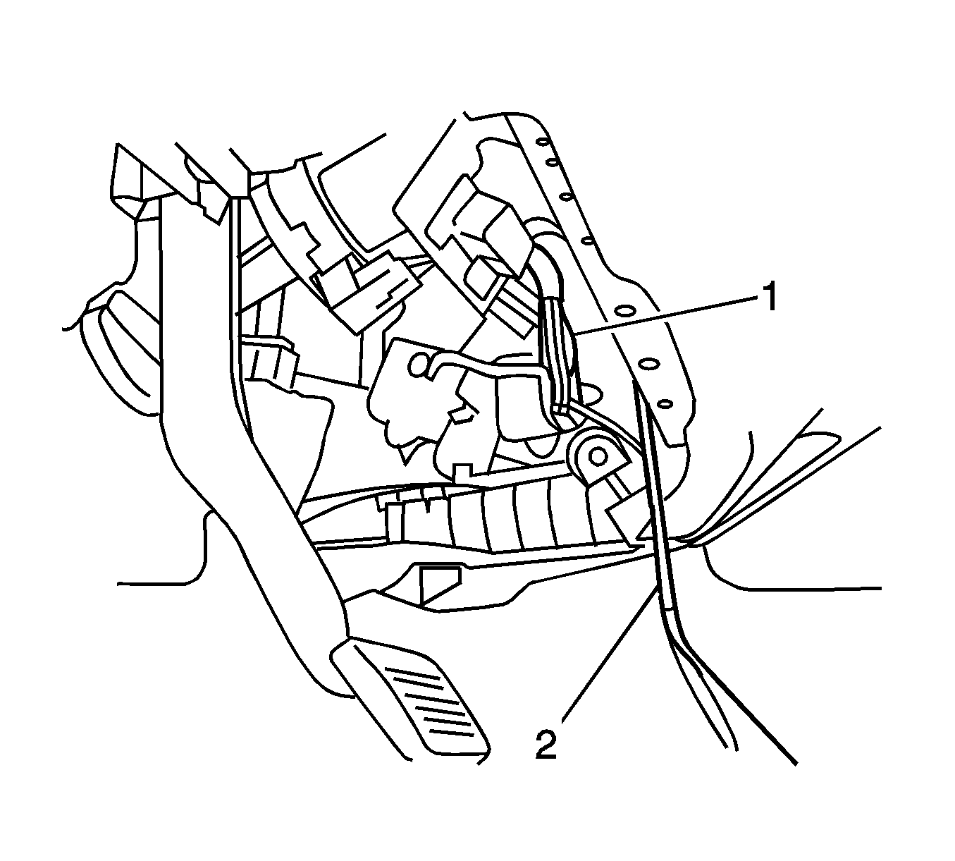
Important: If the vehicle is equipped with trailer electric brake or front off road lights, this wire will be used already.
Notice: Refer to Fastener Notice in the Preface section.
Important: Do not overtighten the rivnuts.
Tighten
Tighten the rivnut to 7 N·m (45 lb in).
Tighten
Tighten the fender flange screws to 7 N·m (45 lb in).
Important: Ensure the wiring is not trapped beneath the fasteners.
Maintain a parallel gap to the windshield reveal molding and luggage rack side rails.
Tighten
Tighten the fasteners to 4.5 N·m (30 lb in).
Tighten
Tighten the screws to 2 N·m (18 lb in).
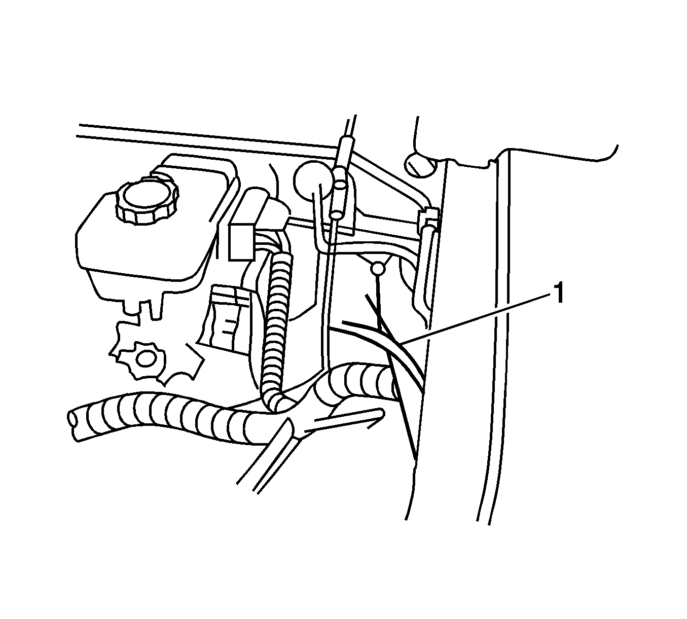
Important: There may be more than one blunt cut wire, all of them are ground wires.
