For 1990-2009 cars only
Brake Pedal Assembly Replacement LHD
Removal Procedure
- Remove the knee bolster. Refer to Driver Knee Bolster Replacement .
- Remove the knee bolster bracket. Refer to Driver Knee Bolster Bracket Replacement .
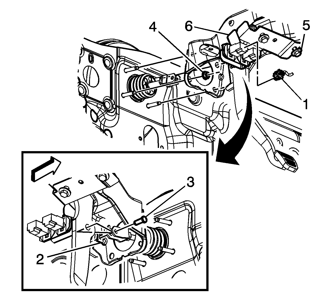
- Disconnect the electrical connectors (1) for the brake switches. Refer to Stop Lamp Switch Adjustment .
- Remove the bolts and lower the steering column.
- Remove the clevis pin retainer (2).
- Remove the clevis pin (3).
- Remove the 4 master cylinder nuts (4).
- Remove the brake pedal bracket bolts (5)
- Remove the brake pedal assembly (6).

Do not disconnect the steering column from the intermediate shaft.
Installation Procedure
- Install the brake pedal assembly (6) on the brake master cylinder studs.
- Finger tighten the mounting bolt (5) to the cowl.
- Install the master cylinder nuts (4).
- Tighten the brake pedal bracket bolts (5).
- Install the clevis pin (3) in the yoke for the brake master cylinder.
- Raise the steering column.
- Install the clevis pin retainer (2).
- Connect the electrical connectors (1) for the brake switches. Refer to Stop Lamp Switch Adjustment .
- Install the knee bolster bracket. Refer to Driver Knee Bolster Bracket Replacement .
- Install the knee bolster. Refer to Driver Knee Bolster Replacement .

Notice: Refer to Fastener Notice in the Preface section.
Tighten
Tighten the nuts to 27 N·m (20 lb ft).
Tighten
Tighten the bolts to 20 N·m (15 lb ft).
Tighten
Tighten the bolts to 27 N·m (20 lb ft).
Brake Pedal Assembly Replacement RHD
Removal Procedure
- Remove the driver knee bolster bracket. Refer to Driver Knee Bolster Bracket Replacement .
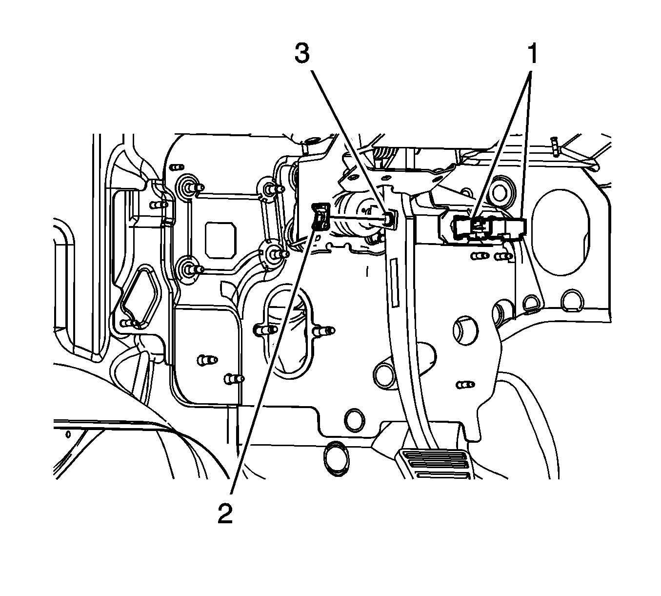
- Disconnect the stoplamp switch and cruise release switch electrical connectors (1).
- Remove the retainer (2) from the clevis pin.
- Remove the brake pedal pushrod clevis pin (3).
- Without disconnecting the upper steering column intermediate shaft, lower and support the steering column. Refer to Steering Column Replacement .
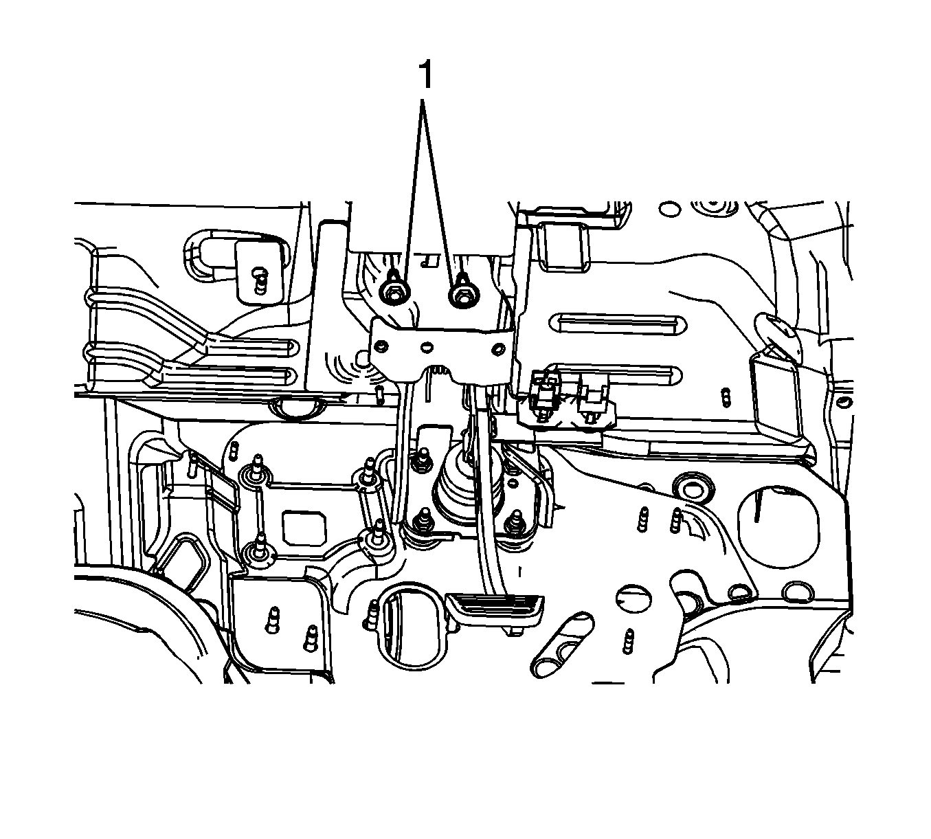
- Remove the 2 upper brake pedal bracket bolts (1).
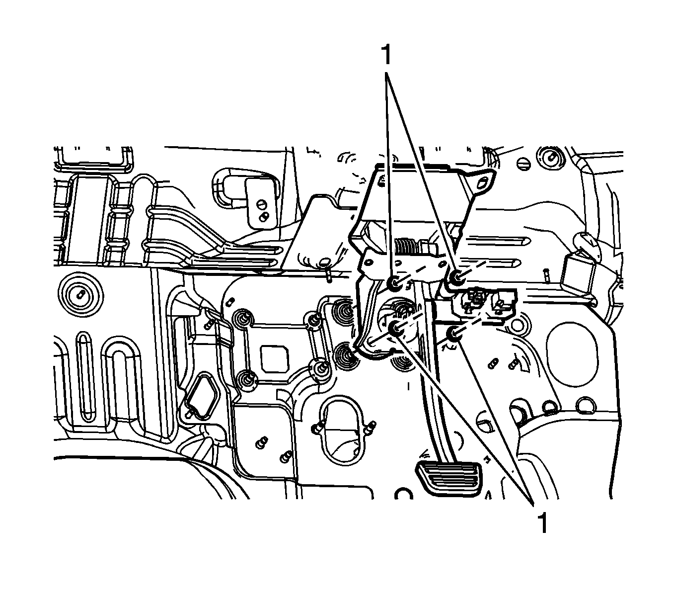
- Remove the 4 brake master cylinder nuts (1).
- Remove the brake pedal assembly.


Installation Procedure
- Install the brake pedal assembly.
- Install the 4 brake master cylinder nuts (1).
- Install the 2 upper brake pedal bracket bolts (1).
- Install the steering column. Refer to Steering Column Replacement .
- Install the brake pedal pushrod clevis pin (3).
- Install the brake pedal pushrod retainer (2).
- Verify the correct installation of the retainer by rotating the retainer 360 degrees.
- Connect the stoplamp switch and cruise release switch electrical connectors (1).
- Adjust the stoplamp switch. Refer to Stop Lamp Switch Adjustment .
- Adjust the cruise release switch. Refer to Cruise Release Switch Adjustment .
- Install the driver knee bolster bracket. Refer to Driver Knee Bolster Bracket Replacement .

Notice: Refer to Fastener Notice in the Preface section.
Tighten
Tighten the nuts to 27 N·m (20 lb ft).

Tighten
Tighten the bolts to 20 N·m (15 lb ft).

The retainer must rotate freely and not become disengaged from the groove in the clevis pin.
