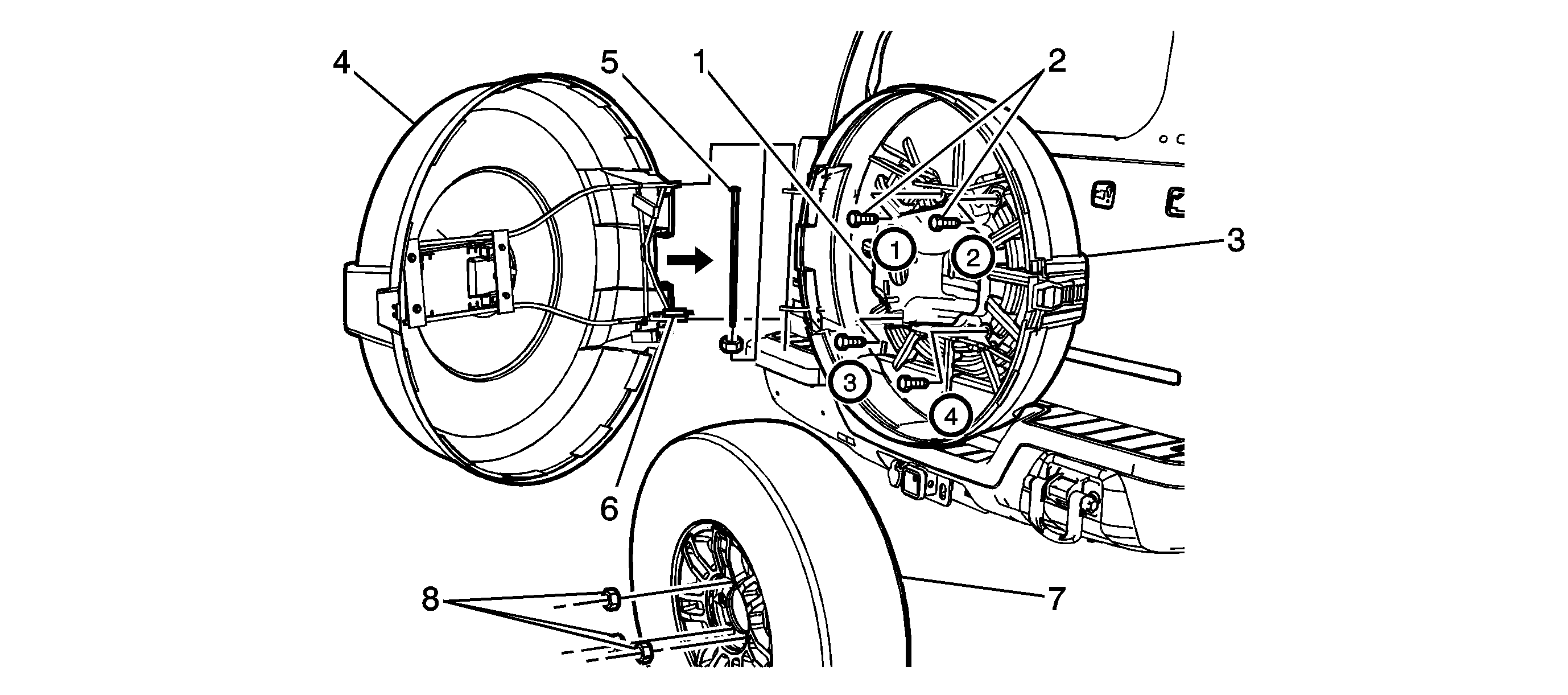
Callout
| Component Name
|
Preliminary Procedures
- Remove the spare tire from the spare tire carrier.
- Remove the 4 nuts from the spare tire carrier studs.
- Remove the spare tire carrier.
- Remove the 4 spare tire carrier studs from the liftgate.
|
1
| Spare Wheel Carrier Assembly
|
2
| Spare Wheel Carrier Bolt (Qty: 4)
Notice: Refer to Fastener Notice in the Preface section.
Tip
| • | Apply LOCTITE® Blue, 242 to the threads prior to installing the spare wheel carrier bolts to the liftgate. |
| • | Tighten the 4 bolts in sequence as shown. |
Tighten
50 N·m (37 lb ft) |
3
| Spare Wheel Stowage Inner Cover Assembly
|
4
| Spare Wheel Stowage Outer Cover Assembly
Procedure
- Align the outer cover hinge to the inner cover hinge.
- If the outer cover sags, remove the 4 bolts holding the outer hinge to the outer cover.
- Place the outer cover in the Full Open position and swing the outer hinge to the closed position.
- Measure from the floor to the top bar of the outer hinge at the outermost vertical mounting plate.
- Using the palm of the hand, pry upward on the outer hinge and re-measure from the floor to the same location as previously measured on the outer hinge.
- Continue using the previous adjustment steps until the proper amount of height of the hinge outer is achieved to obtain the proper alignment of the Inner to Outer panels.
|
5
| Spare Wheel Carrier Hinge Bolt
Tighten
10 N·m (89 lb in) |
6
| Gas Strut Bolt
Tighten
10 N·m (89 lb in) |
7
| Spare Wheel Assembly
|
8
| Spare Wheel Assembly Nut (Qty: 3)
Tighten
136 N·m (100 lb ft) |

