For 1990-2009 cars only
Special Tools
| • | CH 48894 Drive Axle Seal Clamp Pliers |
| • | J 8059 Snap Ring Pliers |
| • | J 35910 Drive Axle Boot Clamp Pliers |
Note: The Double Offset Joint (DO) assembly and it's inner components are NOT serviced. If the DO joint is found to have excessive wear or damaged parts, replace the wheel drive shaft as an assembly.
Disassemble Procedure
- Remove the wheel drive shaft from the vehicle. Refer to Wheel Drive Shaft Replacement.
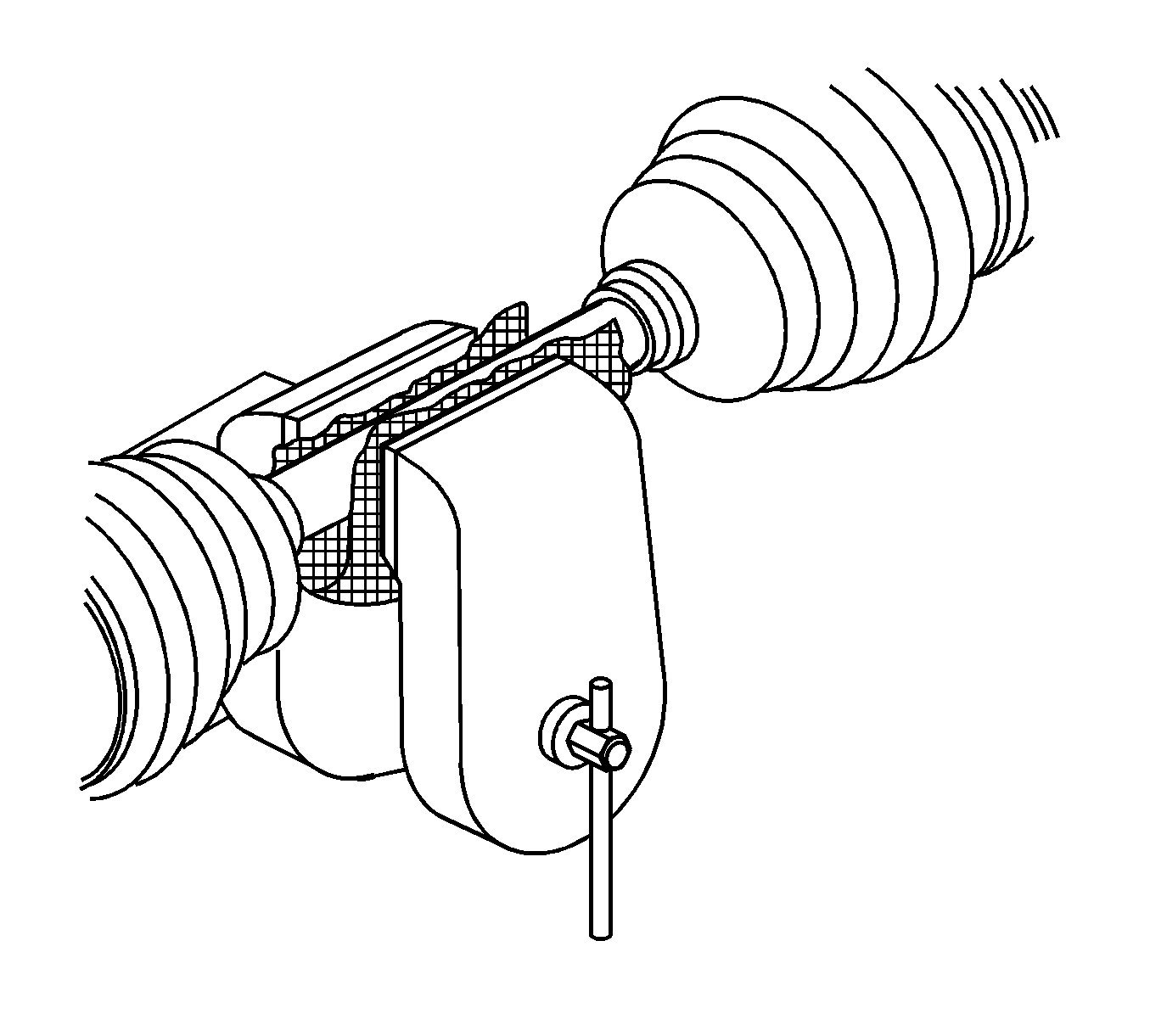
- Install the wheel drive shaft in a soft jawed vise.
- Using a flat-bladed tool, remove and discard the boot clamp from the outer housing and the boot.
- Using a pair of side cutters, remove and discard the boot clamp from the boot and the wheel drive shaft.
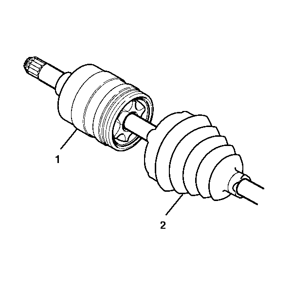
- Remove the boot (2) from the DO joint (1).
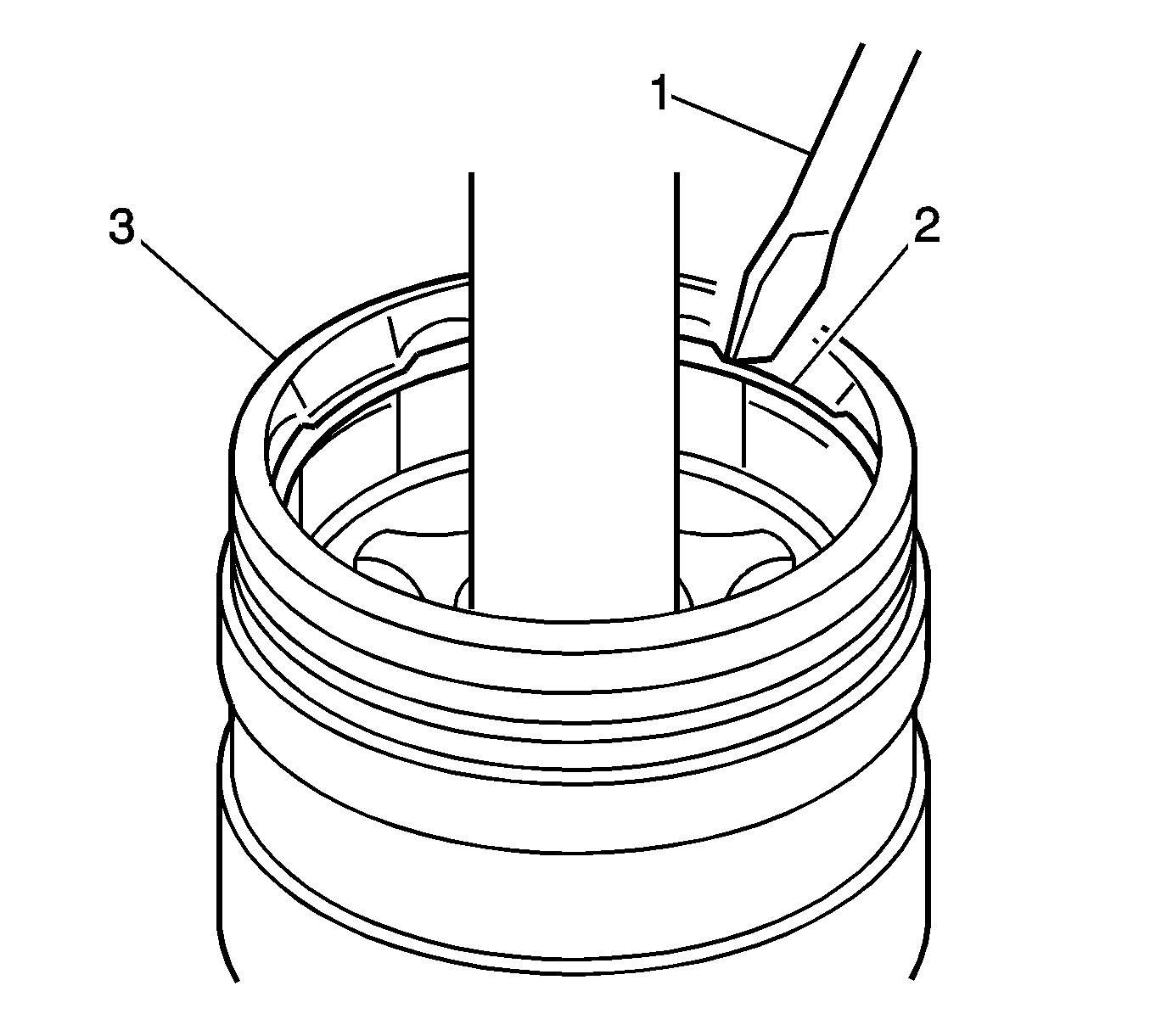
- Using a screwdriver (1), remove the retaining ring (2) from the DO joint housing (3).
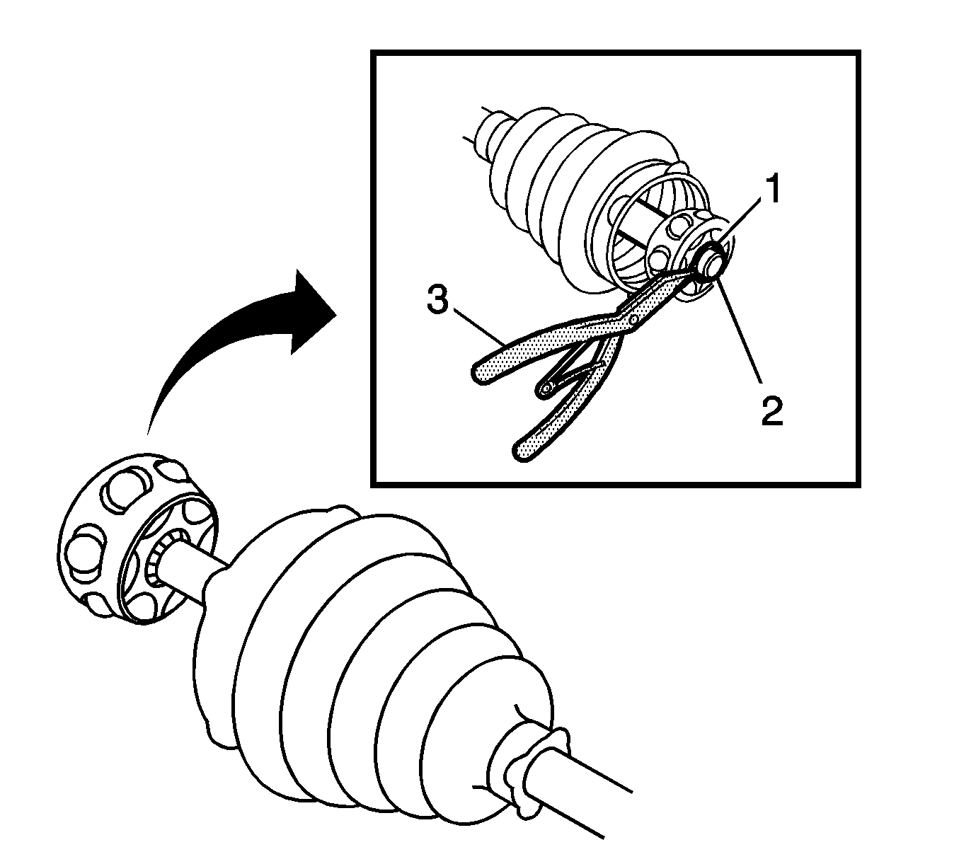
- Using the J 8059 pliers (3), remove the retaining ring (1) from the wheel drive shaft (2).
- Remove the cage assembly (1) and the boot (3) from the wheel drive shaft (2).
- Remove the lubricant from the cage and the DO joint housing. If either the cage or the DO joint housing shows signs of excessive wear or damage or the bearings have a dull surface, replace the wheel drive shaft as an assembly.
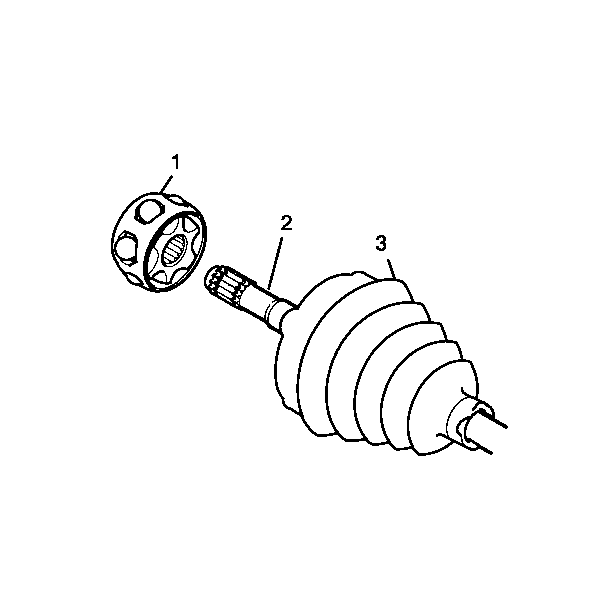
Note: The wheel drive shaft are serviced as an assembly.
Assemble Procedure
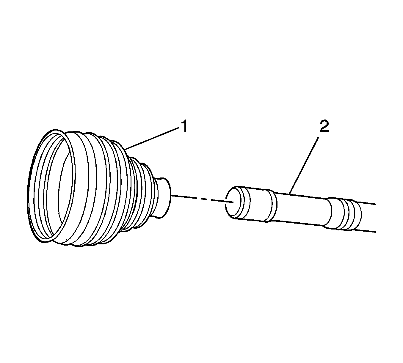
- Position the boot and the clamps (1) on the wheel drive shaft (2).
- Ensure that the boot (1) is properly seated in the groove (2) in the wheel drive shaft (3).
- Install the cage assembly (1) on the wheel drive shaft (2).
- Using the J 8059 pliers (3), install the retaining ring (1) on the wheel drive shaft (2).
- Using a screw driver (1), install the retaining ring (2) in the DO joint housing (3).
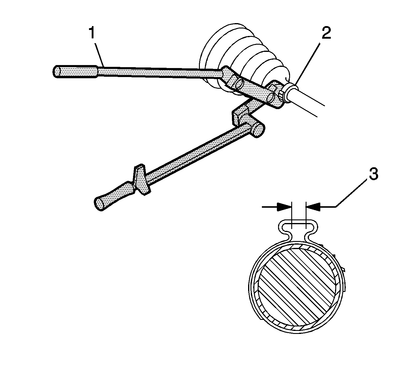
- Using the J 35910 pliers , breaker bar, ratchet and or torque wrench (1), close the boot clamp (2) until the gap (3) measures 2.15 mm (0.085 inch).
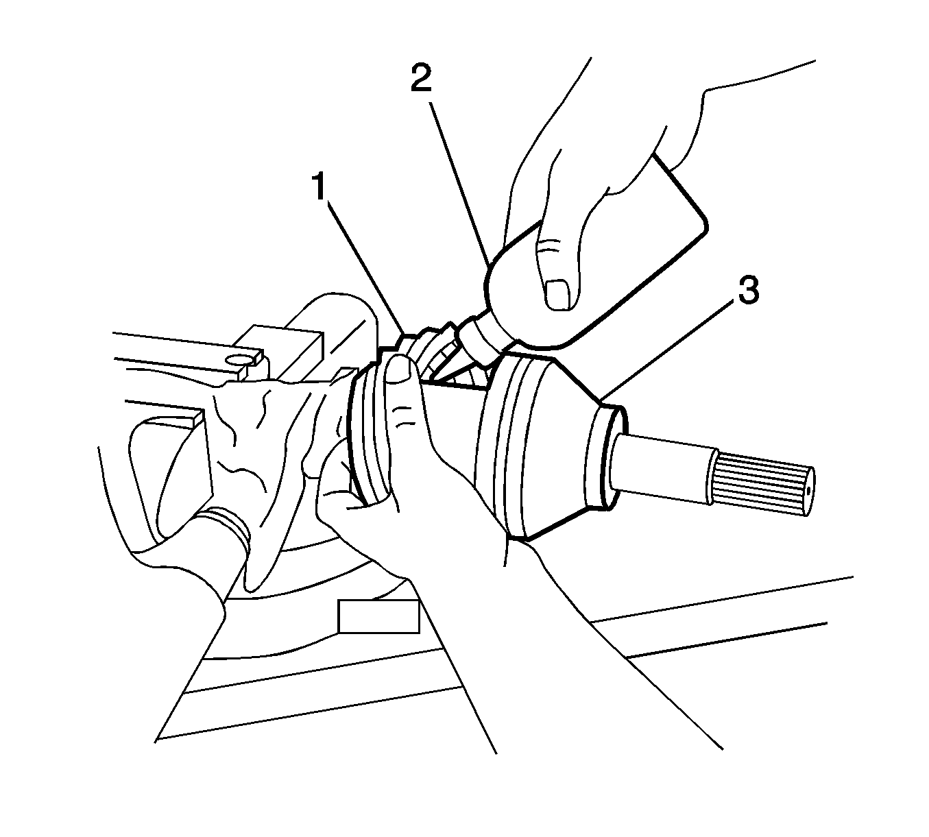
- Place approximately half of the lubricant (2) inside the boot (1) and the remaining lubricant in the DO joint housing (3).
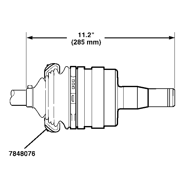
- Check the inboard stroke position.
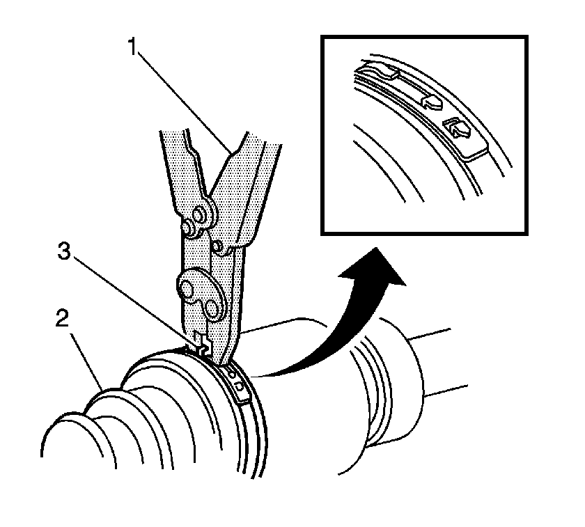
- Using the CH 48894 pliers (1), close the boot clamp (3).
- Move the DO joint in a circular motion 4 or 5 times to distribute the lubricant within the DO joint housing.
- Remove any excess lubricant from the wheel drive shaft.
- Install the wheel drive shaft in the vehicle. Refer to Wheel Drive Shaft Replacement.
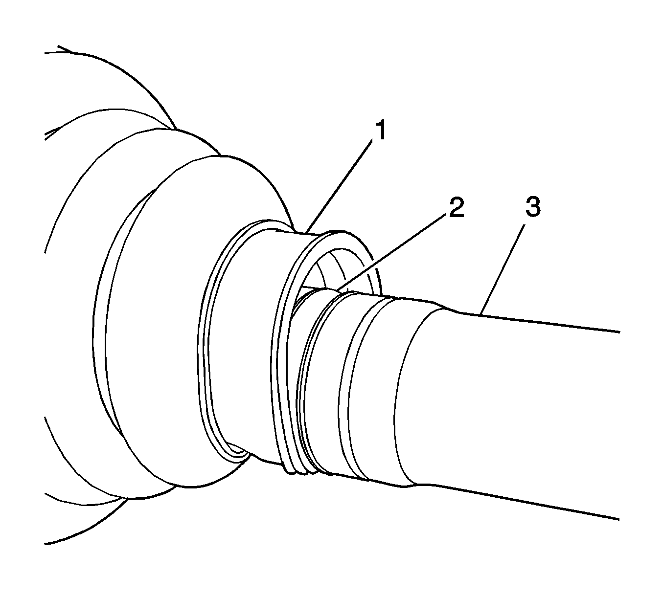


Note: Ensure that the retaining ring is properly seated in the DO joint housing.
