Removal Procedure
- Position the tires in the straight ahead position by turning the steering wheel.
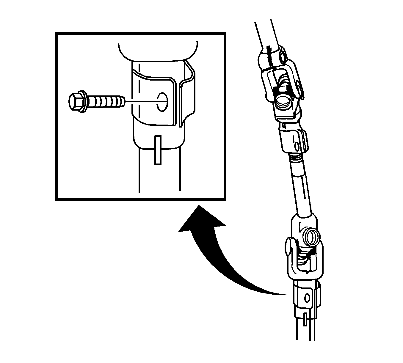
- Remove the intermediate shaft.
- Remove the front tire and wheel assemblies. Refer to Tire and Wheel Removal and Installation .
- Drain the power steering fluid from the rack and pinion.
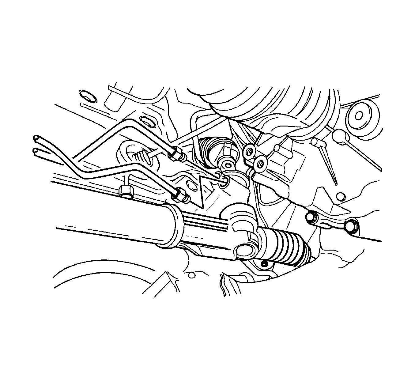
- Disconnect the steering gear inlet and outlet pipe fittings.
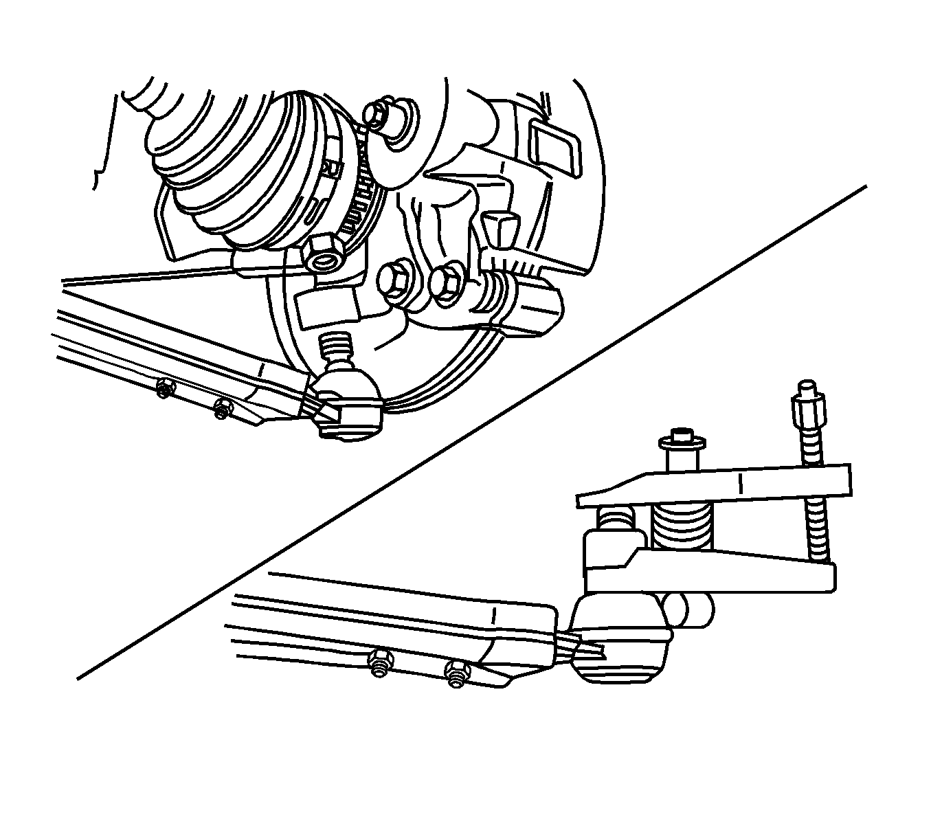
- Remove the outer tie rod hex nuts. Refer to Rack and Pinion Outer Tie Rod End Replacement .
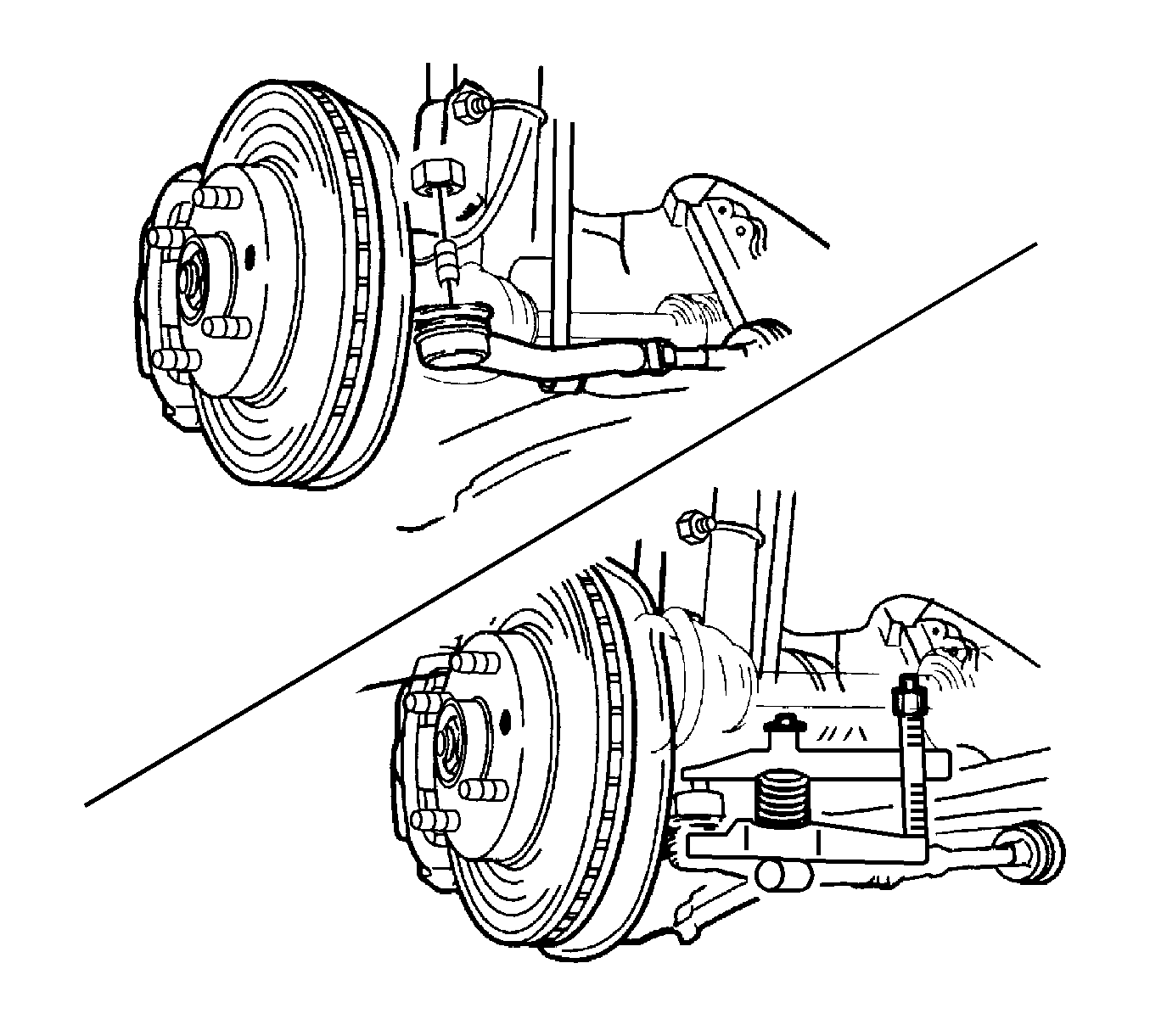
- Remove the ball joint hex nuts and disconnect the stabilizer shaft from the knuckle by removing the stabilizer shaft link assembly. Refer to Stabilizer Shaft Link Replacement .
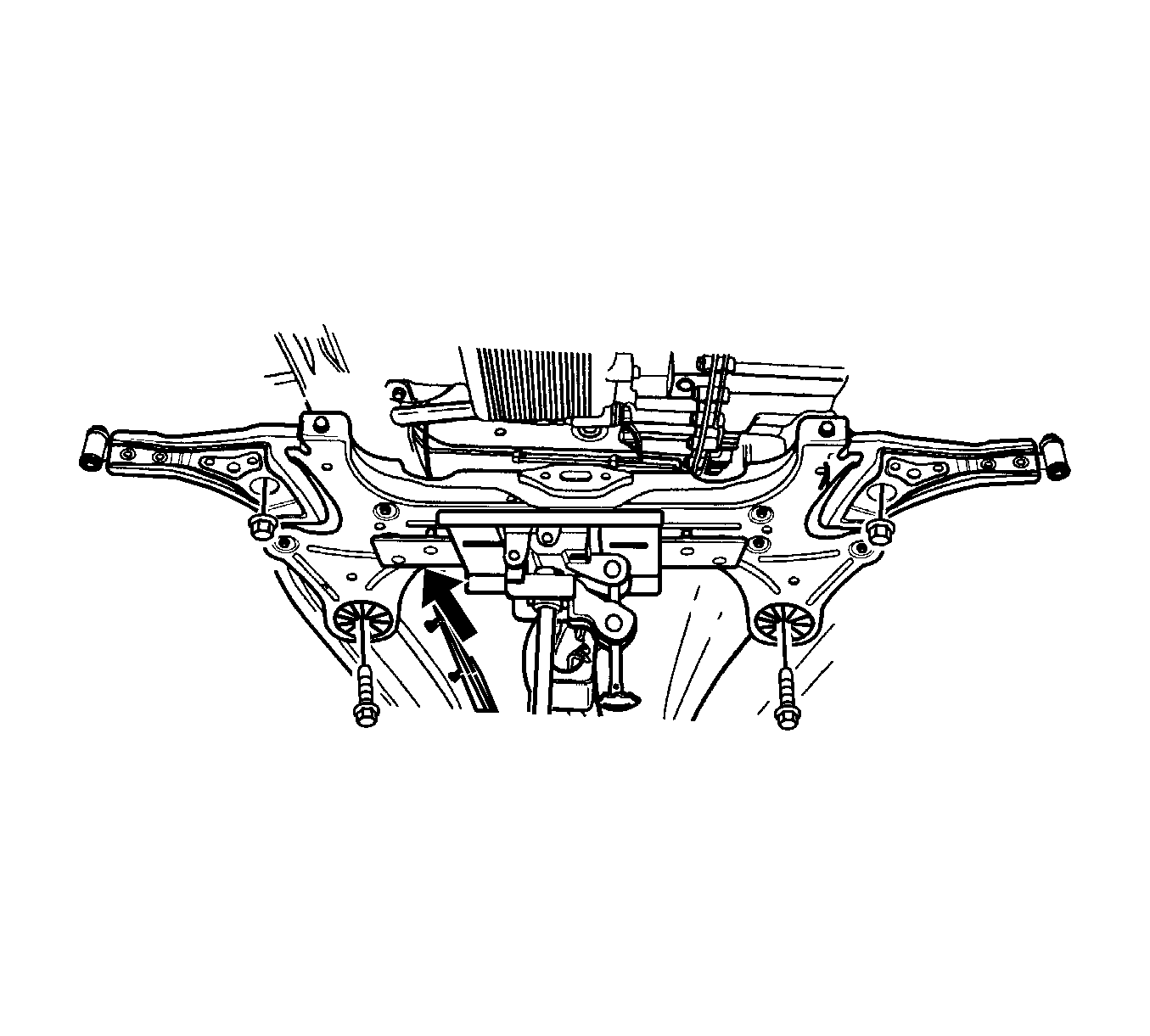
- Remove the cross member by removing the nuts and bolts to the underbody.
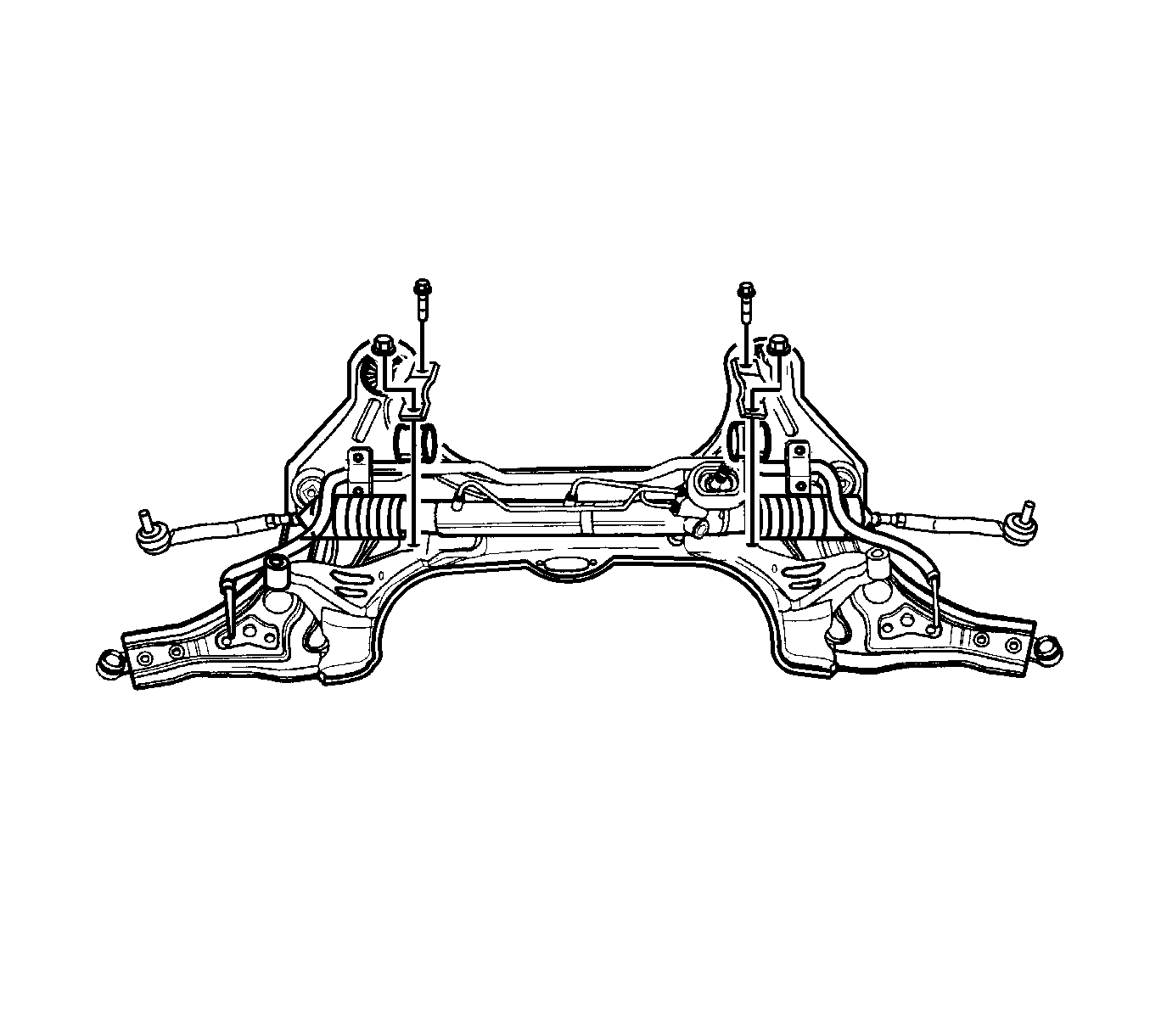
- Remove the rack and pinion assembly by disconnecting the steering gear retaining bracket nuts.
Installation Procedure
- Install the rack and pinion assembly by connecting the steering gear retaining bracket nuts.
- Install the cross member by tightening the nuts and bolts to the underbody.
- Install the ball joint hex nuts and connect the stabilizer shaft to the knuckle by tightening the bolt with stabilizer shaft link assembly. Refer to Stabilizer Shaft Link Replacement .
- Install the outer tie rod hex nuts. Refer to Rack and Pinion Outer Tie Rod End Replacement .
- Connect the steering gear inlet and outlet pipe fittings.
- Install the front tire and wheel assemblies. Refer to Tire and Wheel Removal and Installation .
- Refill the power steering fluid.
- Install the intermediate shaft.
- Inspect the vehicle. Refer to Preliminary Alignment Inspection and Straight Ahead Inspection .
- Measure the wheel alignment.
- If necessary, adjust the front toe. Refer to Front Toe Adjustment .
Notice: Refer to Fastener Notice in the Preface section.

Tighten
Tighten the steering gear retaining bracket nuts to 50 N·m (37 lb ft).

Tighten
Tighten the cross member by tightening the nuts and bolts to the underbody to 150 N·m (111 lb ft).

Tighten
| • | Tighten the ball joint hex nuts to knuckle to 45 N·m (33 lb ft). |
| • | Tighten the bolts of the stabilizer shaft to the knuckle to 45 N·m (33 lb ft). |

Tighten
Tighten the outer tie rod hex nuts to 45 N·m (33 lb ft).

Tighten
Tighten the nuts of the steering gear inlet and outlet pipe fittings to 22 N·m (16 lb ft).
Notice: When adding fluid or making a complete fluid change, always use a power steering fluid meeting GM Spec. No. 9985010 or equivalent. Fluid for cold climates is also available through GM Dealerships; refer to Specifications for further information. Failure to use the proper power steering fluid can cause power steering hose and seal damage, fluid leaks and pump failure.

