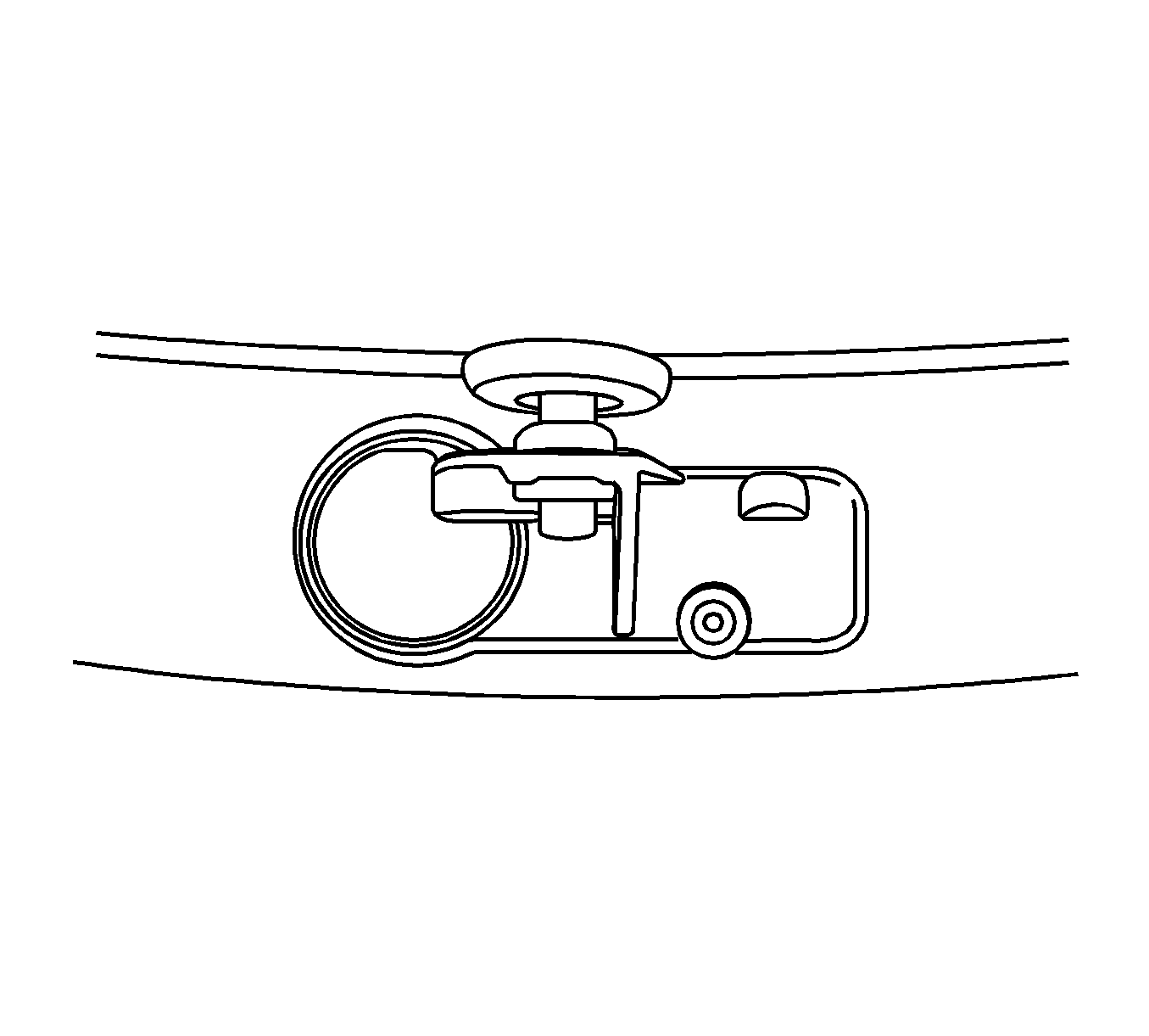
For 1990-2009 cars only
Removal Procedure
- Raise and support the vehicle. Refer to Lifting and Jacking the Vehicle.
- Remove the tire and wheel assembly from the vehicle. Refer to Tire and Wheel Removal and Installation.
- Remove the tire from the wheel. Refer to Tire Dismounting and Mounting.
- Remove the TORX screw.
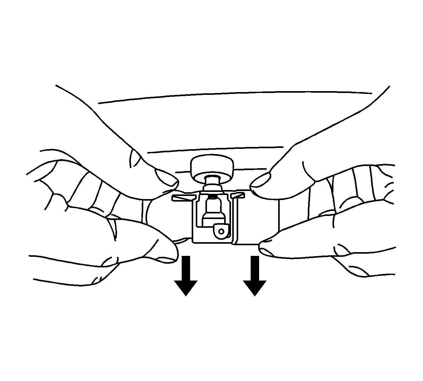
- Carefully pull the enclosure straight off of the valve.
- Cut the rubber bulb off of the valve stem.
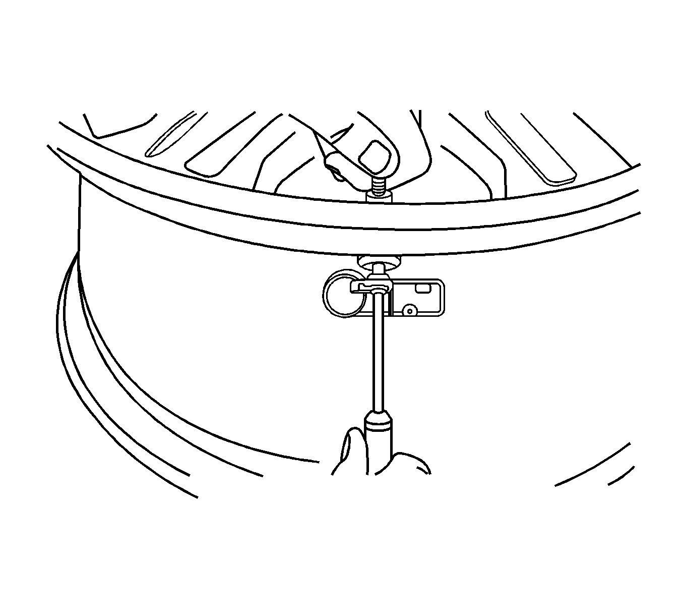
- Attach the tire valve stem mounting tool, or equivalent, to the valve stem.
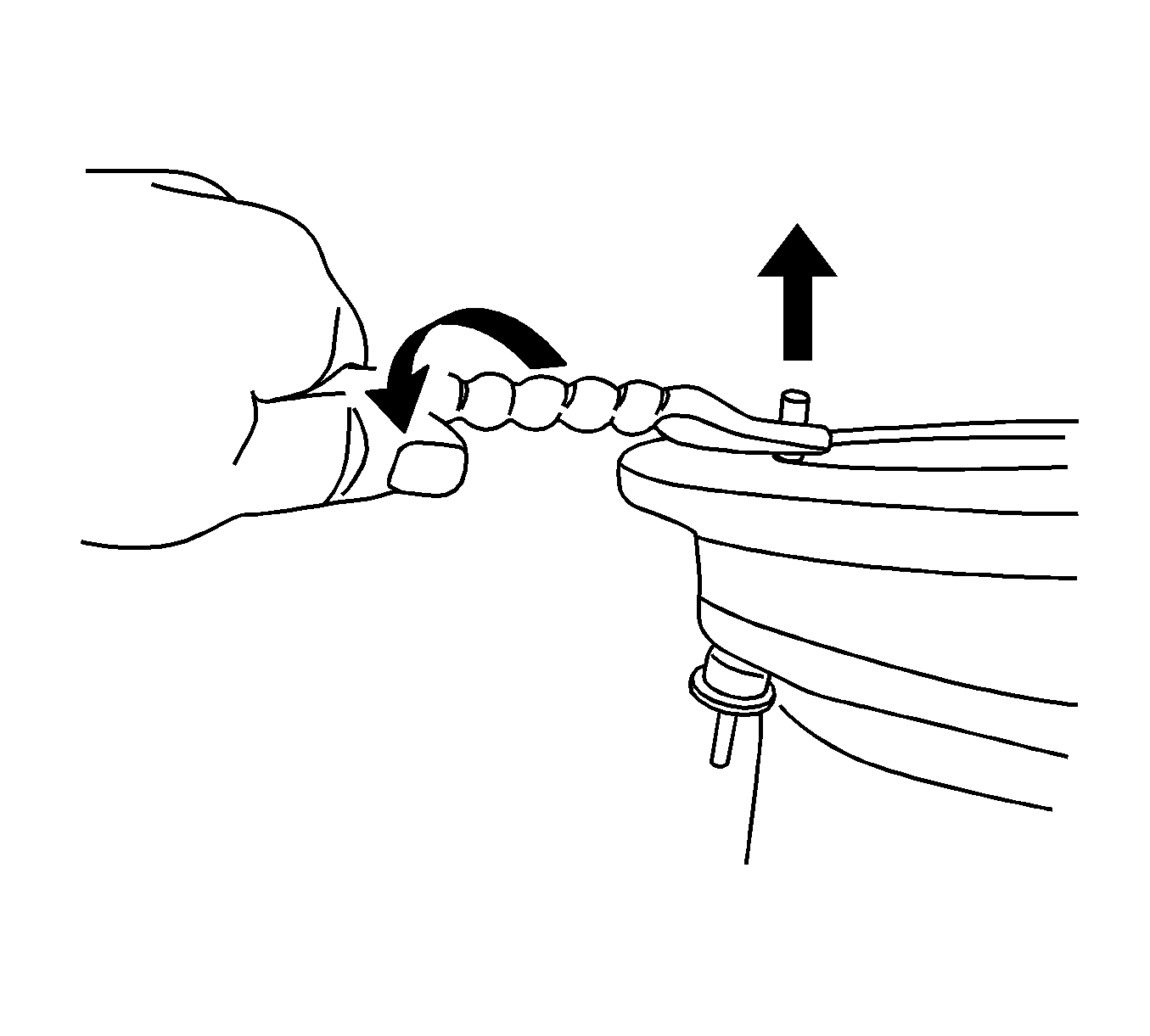
- Pull the valve stem through the rim in order to remove the valve stem.
Notice: Do not scratch or damage the clear coating on aluminum wheels with the tire changing equipment. Scratching the clear coating could cause the aluminum wheel to corrode and the clear coating to peel from the wheel.
Installation Procedure
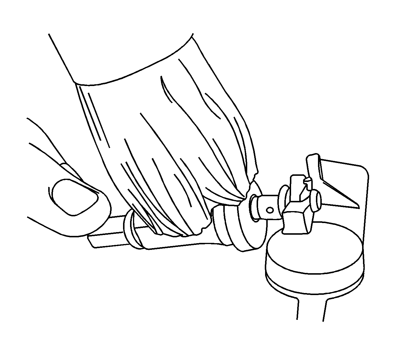
- Hold the valve stem WITHOUT the valve core.
- Assemble the NEW tire pressure sensor snap-in enclosure to the valve stem and install a NEW TORX screw. Tighten the screw until the valve begins to rotate in the hand.
- Apply GM Goodwrench Rubber Lubricant, GM P/N 12345884 (Canadian P/N 5728223), or equivalent, to the rubber portion of the valve stem and the top of the enclosure.
- Align the sensor with the valve stem hole in the wheel.
- Attach the tire valve stem mounting tool, or equivalent, to the valve stem.
- Position the tire valve stem mounting tool, or equivalent, on the correct notch.
- Pull the valve stem and the sensor in the direction parallel to the valve hole axis.
- Ensure the valve stem and the tire pressure sensor are installed correctly. The rubber bulb of the valve is resting against the rim. The front face of the enclosure is NOT touching the rim.
- Install the tire to the wheel. Refer to Tire Dismounting and Mounting.
- Install the tire and wheel assembly to the vehicle. Refer to Tire and Wheel Removal and Installation.
- Lower the vehicle.
- Configure the tire pressure monitor system. Refer to Tire Pressure Monitor System Configuration.
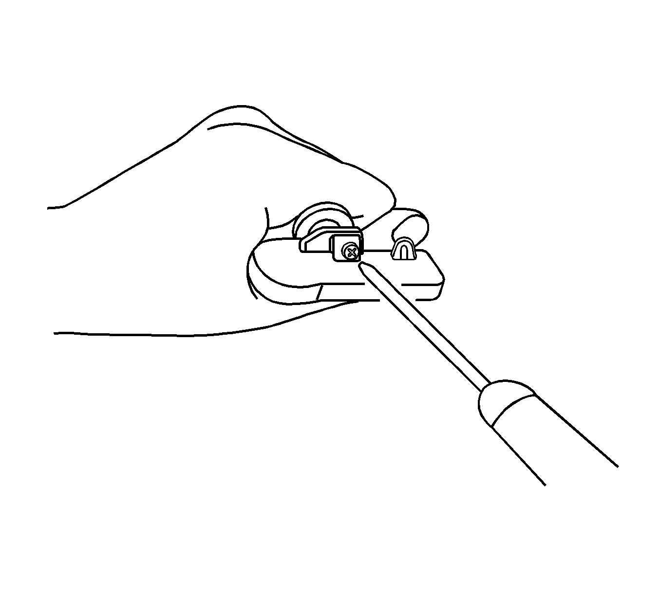
Important: Do not use the valve by itself without attaching the snap-in tire pressure monitor sensor part. Do not re-use the old screw or the snap-in valve. Always install a NEW screw and a NEW snap-in valve.
Important: Do not hold the snap-in enclosure while installing the screw as this will lead to overtightening.
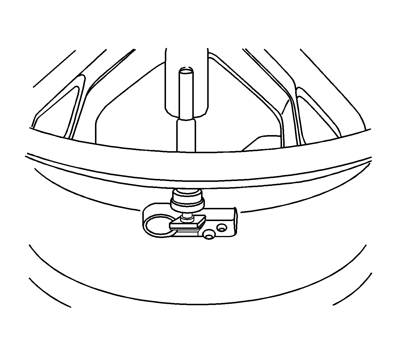
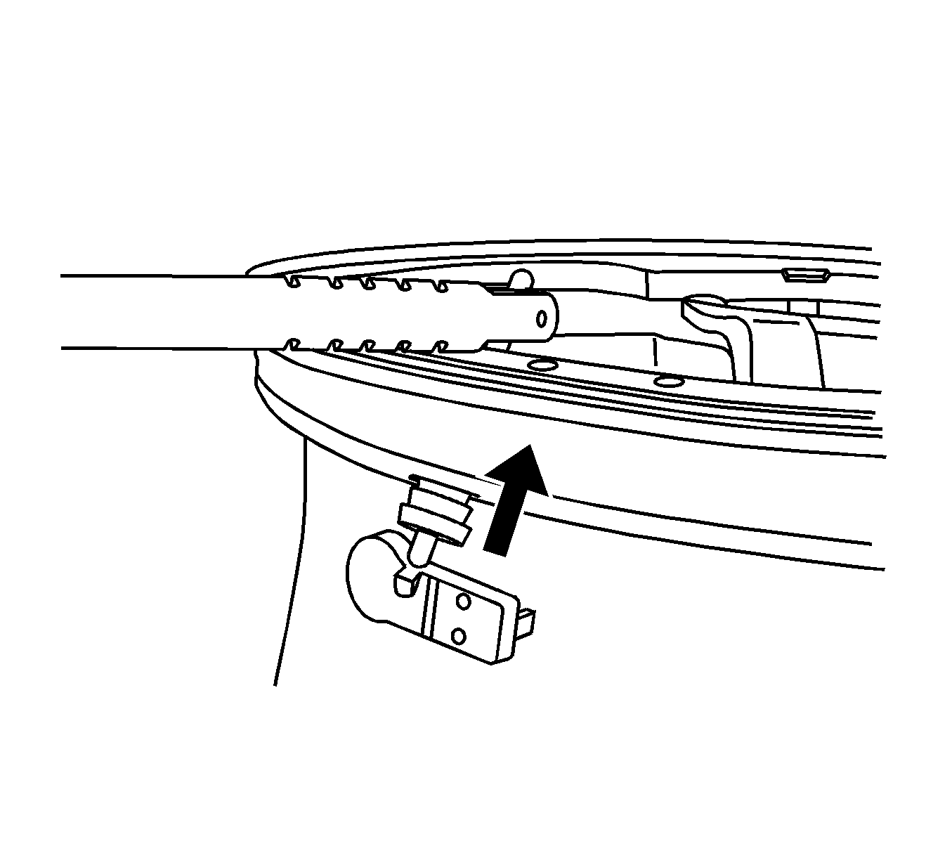
Important: Do not pull the valve stem and the sensor at a different angle than the valve hole axis.
